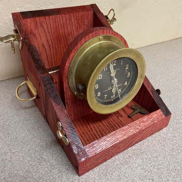
Summary – Final dimensions as 10″ H, 9″ W, 6″ D. The two critical elements are that the two halves fall equally when opened to provide a stable base for the clock to sit when in use, and that the box hinge open without collision with the top of the clock face.
There are no officially documented blueprints for the construction of an M 1 or 2 Message Center Clock box (that I could find), although several pictures are available online. One such picture was available from the IMA website, which gave outside dimensions of the box as 9″ W x 4.5″ D x 10″ H (although these dimensions ended up not working on our example with the materials we had).
The box appears to be made of oak, based on the grain pattern and has no visible fastening on the outer surfaces to indicate nails or screws. This would suggest the construction is primarily held together with wood glue, with possible pegs or wedges acting as secondary support. Given that I do not have a box to deconstruct for reverse engineering, I cannot verify the exact construction. Tongue and groove reinforcement does not seem to be likely, however, given the lack of evidence on the internal edges.
When I constructed this box, I purchased readily available 3/4 inch oak boards from the local hardware store. These are listed online at Menards or Home Depot. It is not unlikely the genuine box was made from different thickness lumber, as modern dimensional lumber varies from historical dimensions due to construction conveniences (hence why a 2×4 is measured at 1.5 x 3.5). In any case, this thickness appears fairly appropriate to the pictures available. I purchased 10″ wide boards, which were 9.5″ dimensionally. This allowed for the correct width of the box without need for edge gluing. I Measured the clock and I had to be just under 6″ (around 5 7/8 inch or so), so this left roughly 1.5 inches in the internal area if two 3/4 width boards are factored in. When placed on its backboard, the depth of the clock was just under 4 inches. This would not have worked with the dimensions available on IMA, since two board thickness would have left only 3 inches on the internal area. So I opted to go with a 6 inches of depth for the box. This left final dimensions as 10″ H, 9″ W, 6″ D.
The box front and back boards were 7 1/2 inches wide, to allow for the side pieces to run to the front, as it looks in the photos. These were overcut to around 10.5 inches, to allow cutting width of the blade when making the opening. This was also true for the side pieces, which were 6 inches wide. The angle of the box cut was approximately 30 degrees. I first attempted a 45 degree angle but the height of the box appeared odd. 30 degrees allowed a good fit between the top and bottom portions of the box. To do this correctly, I made the cut from the back ends of the side pieces, marking the start of the cut at 5 inches, and setting the saw miter to 30 degrees. Doing these cuts at the same time prevents angle ambiguity in resetting the miter, which prevents headaches in future assembly. Cut both side pieces, then partially assemble the bottom portion with both front and back. Mark the area where the bottom of the angle meets the front piece and cut the front with a 30 degree angle on the blade. You can trim the excess wood from the top before final assembly. For the back piece, since there is a hinging mechanism, the angle would impede on opening, so make a straight cut at 5 inches. This should be verified with the dry assembly as well. The bottom and top caps can then be cut based on how the pieces fit together, or roughly 7 1/2 inches W x 4 1/2 inches. Test fit these pieces together, trim as needed, and glue or screw into place the pieces. I found pre-drilling and countersinking the holes are needed, as oak is prone to splitting. For a static display box glue might work, but if this used as a transit case, screws or dowls would be needed for durability. This example will be used as a transit case thus screws were used. This introduces the holes seen in the photo, which isn’t in the originals, so dowls may be an option if you want an unblemished example.
The next factor to determine was construction of the backboard itself. The wood edge around the clock looked to be around 1/4 inch, so I cut a roughly 6 1/2 W x 7 1/2 H slab. This allowed me to find the center of the semicircle by placing a compass where it met around the top and both sides of the boards. I scored a line to mark the edge of the semicircle and cut the circle out with multiple cuts on the table saw, finished with a belt sander to meet the line. This could also be done on a bandsaw or scroll saw, but I wanted to get cleaner edges. I placed the clock on the centerline of the board and roughly placed it where all edges looked equal. This allowed me to mark the top hole for the screw and pre-drill. This let the clock hang so I could mark the bottom two holes when it was partially installed. The backboard can then be fixed into place within the box by drilling two holes into the bottom of the box and running screws into it. Additional support can be provided by a screw in the front of the backboard, running through the back of the box. Just make sure it is a short enough screw that it does not penetrate through the back.
Stain and a layer or two of protective coating (I prefer Tung Oil), then you can install the hardware. Hardware itself is available at any hardware store, but mine came from Rockler.
Carpentry and article by Troy
