
Appendixes available on request to validated .mil users
HF Radio Deployment For Voice and Data
130 FAB, Annual Training (AT) 2019
CW2 J. M., Net Tech 25 June, 2019
- Introduction
- Equipment
- Antenna Placement
- Radio Integration
- AFATDS Integration
- Conclusion
- Appendices
- References
Introduction
The 130 FAB was tasked with controlling fires for all subordinate firing BN’s (4 in total) during AT 2019. Both BDE and subordinated BN’s were located in Fort Riley, KS. High Frequency (HF) radio, Joint Capabilities Release (JCR), and FM SINGCARS were available for data communications; while HF radio and FM SINGCARS were available for voice communications. Mission Command Information Systems (MCIS) and SATCOM were unavailable during this training exercise. The operational PACE plan prioritized HF communications for both voice and digital. This document describes how the 130FAB established reliable HF communications for both voice and data during the training exercise.
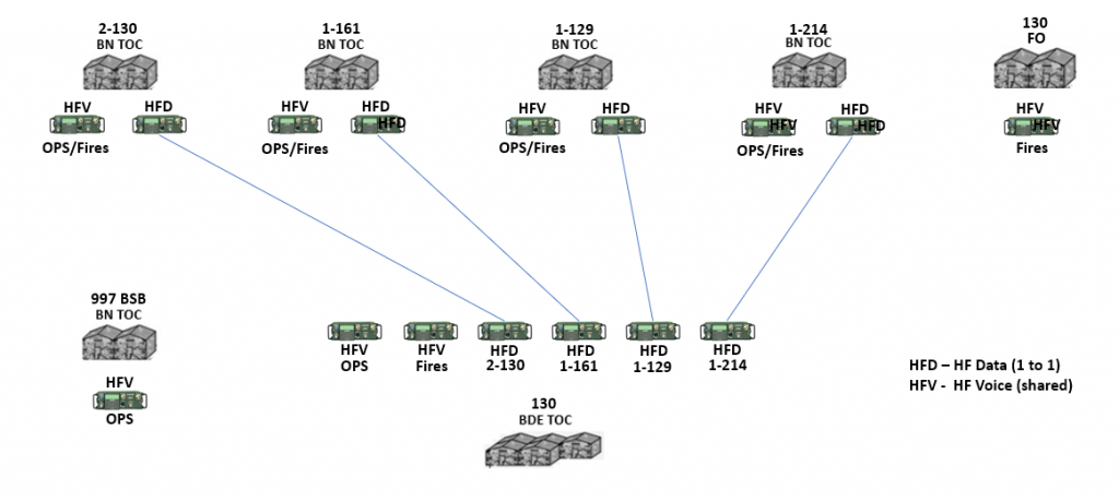
High-Level Architecture
Equipment (R = Required, O = Optional, # = Quantity)
BDE:
(R)(6) AN/PRC 150 HF Radios
(R)(6) RF-1944 Antenna Kits
(R)(6) OE-254 Antenna Kits
(O)(6) Metal Keyrings or D-rings (for mounting balun via pulley)
(O)(6) Zip ties (for mounting balun via pulley)
(R)(6) LMR 400 Coax Cable (or equivalent) equipped w/ BNC (F) to BNC (F)*
(R)(4) HF Radio Serial Data Cable (PPP Cable)**
(R)(2) IP6600 Serial/IP Data Routers (AC Power)
(R)(1) Laptop pre-loaded with Harris Radio Programming Application (RPA) and NRDI software
(R)(1) Layer 3 Switch (capable of creating multiple secondary IP addresses per interface)
(R)(1) Secure Key Loader (SKL) loaded with appropriate COMSEC
(R)(*) AFATDS
(R)(*) Ethernet networking cable (e.g., CAT 5e)
*Needs (quantity, type, length, etc.) will vary based on TOC layout, number of systems (e.g., AFATDS), and other unit specific requirements.
** The PPP cable should be included in the man-pack configuration for the PRC-150. The part number for the cable is 10535-0775-A006.
BN:
(R)(2) AN/PRC-150 HF Radios
(O)(2) RF-1944 Antenna Kits*
(O)(2) OE-254 Antenna Kit**
(O)(2) Metal Keyrings or D-rings (for mounting balun via pulley)
(O)(2) Zip ties (for mounting balun via pulley)
(R)(1) HF Radio Serial Data Cable (PPP Cable)
(R)(1) AFATDS
(R)(1) SKL loaded with appropriate COMSEC
(R)(1) Laptop pre-loaded with Harris Radio Programming Application (RPA) and NRDI software
*Other HF antenna types (man-pack whip, AS-4701/VRC, etc.) may be used instead. Antenna design and utilization should be based on unique variables associated with the mission (e.g., terrain, distance, TOC layout, available equipment, etc.).
*The RF-19440-AT 150 Antenna Kit requires a vertical platform to elevate the balun and elements of the dipole. The antenna can be elevated using nearly any vertical platform (e.g., OE-254, a tree, or even an M577 queen mast).
Antenna Placement
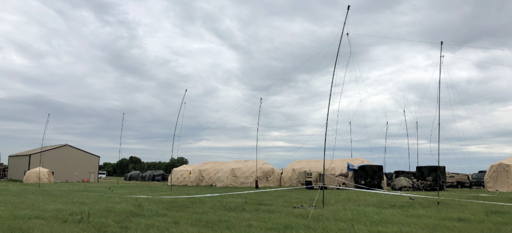
The BDE utilized 6 different HF radios (2 voice, 4 digital) paired with 6 RF-1944 antennas during AT 2019. The radios were required to communicate with subordinate BN’s deployed within the Ft. Riley area of operations (AO). The BDE S6 section conducted a terrain/mission analysis, and determined an average of the various azimuths in the direction of the subordinate units; which was used to plan the deployment of an antenna field which centered the broad (strong) side of the propagation signal to the BN’s. The chosen antenna architecture would potentially support a vast geographic separation between the BDE and each BN (to simulate a potential real-world scenario); while simultaneously supporting all units located within the confined AO.
The S6 coordinated placement of the antenna field with BDE operations; who allocated an entire (long) side of the operations center (TOC). The antenna field placement required a significant physical footprint (approx. 330’ x 50’); and was required to be as close to the TOC as possible (limited by available cabling).
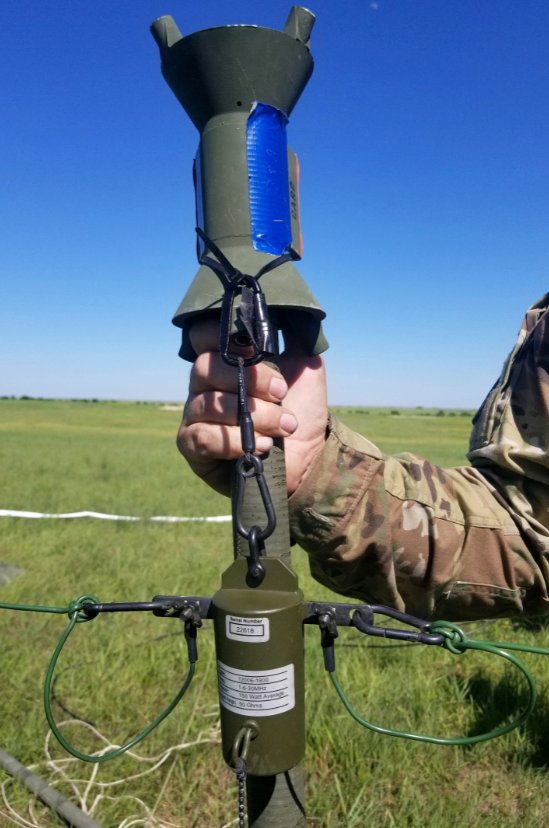
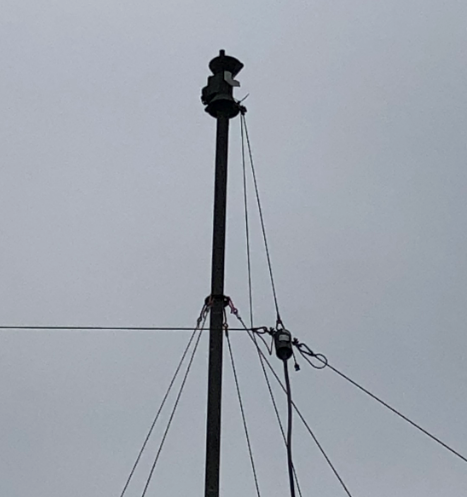
Six antennas were deployed in an Inverted Vee configuration; and were deployed in accordance with the HARRIS RF-1944 installation/deployment manual. Each antenna was mounted to an OE-254 mast, extended to a height of approximately 33’. The balun’s were mounted to the OE-254 feed cone using a zip tie and d-ring (see Figure 1A). The zip tie and d-ring created a pulley system, which allowed operators to lower and raise the balun once the OE-254 was emplaced (see Figure 1B).
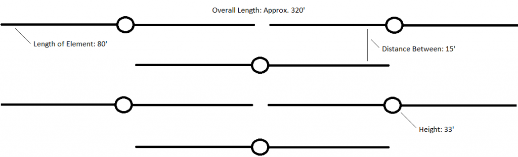
Each element of the antenna was fully extended, resulting in a 160’ Inverted Vee antenna. The diagram outlined in Figure 1C shows the bird’s eye view of how the antenna field was installed. The first antenna in the formation (on the bottom of Figure 1C) was approximately 20’ from the center of the S3 portion of the TOC. All antennas were equipped with LMR-400 coaxial cables (2×200’, 3×150’, 1×87’); and all cables ran into the S3 portion of the TOC.
The antenna placement at each BN varied. Some BN’s deployed Inverted Vee’s using RF-1944 and an OE-254 (similar to BDE). Some BN’s deployed Inverted Vee’s mounted to masts on the M577 FDC tracks. Others utilized man-pack whips, AS-4701/VRC’s, or whatever was available (or whichever provided the most efficient and reliable connection to BDE).
Radio Integration
Fifteen (15) HF PRC-150 radios were used to link communications between BDE and BN’s during the training exercise. The distribution of those radios consisted of the following:
BDE –
[4] Data Radios
[3] Voice Radios
BN –
[1] Voice Radio
[1] Data Radio
All voice radios across the BDE were loaded with the same configuration, using the Harris Radio Programming Application (RPA) software. The voice configuration leveraged the Automatic Link Establishment (ALE) radio mode; which consisted of a single channel group, 5 channels, 5 frequencies1 (ranging from 2 – 14 MHz), and 8 different stations. Appendix A2 provides the step-by-step instructions that were taken to program each voice radio.
The data radios across the BDE were loaded with slightly different configurations; which were also built using the Harris RPA. The data configuration leveraged the Harris 3G – IP Networking radio mode. Four channel groups were created, each representing a one-to-one link between each firing BN and the BDE.
The BDE was only allocated 10 HF frequencies to distribute between the 4 channel groups. This would generally be considered inadequate3; however, all units within the AO were well within range of ground wave propagation, which negated the need for a distributed range of frequencies needed to communicate reliably. A larger geographic separation would require a much larger pool of frequencies per channel group – to account for atmospheric changes (e.g., weather, time of day, etc.).
All radios resided on the same wireless radio subnet, which allowed any BDE programmed radio to communicate with any other BDE programmed radio as long as they were set to communicate on the same channel group. Channel groups were generally assigned to BDE/BN pairs, to simulate a direct dedicated link. Each radio also resided on a unique subnet for their respective local area network (LAN); and generally acted as a gateway (or Exit Router) for any local systems utilizing the radios as a data transport (e.g., AFATDS).
The BN architecture consisted of the radio being directly connected to an AFATDS system (a.k.a. PPP Serial Direct Method). This connection required a PPP serial cable to interconnect the AFATDS and the radio. Step-by-step instructions for establishing a connection between AFATDS and an AN/PRC-150 can be found in Appendix B.
IP address settings for the radio wireless network, the IP network used to communicate with computers (e.g., AFATDS), and all IP routing information were contained within the configuration. The 130 FAB S6 leveraged a generic FAB data and voice RPA to integrate HF data communications in the environment. The generic RPA configurations can be found in Appendix C4.
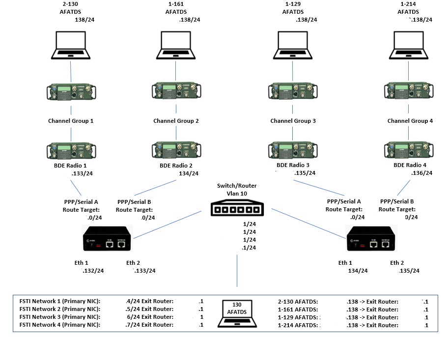
The BDE architecture was slightly more complex. It consisted of multiple AFATDS interconnecting with the 4 BN radios via an Ethernet IP network. The S6 team leveraged the existing Ethernet network interface cards on the AFATDS systems to tie into an Ethernet LAN, which was distributed using a layer 3 Cisco Switch. The switch was then connected to a pair of IP 6600 routers. The routers then communicated with the radios via a PPP serial link. This architecture allowed AFATDS systems to route packets through an existing Ethernet LAN, through any of the interconnected radios, and eventually to the desired BN AFATDS. The design was flexible enough to allow a single or multiple AFATDS to communicate with all BDE AFATDS. See Figure 2A for the LAN/WAN architecture.
1 The HF frequency range allocation to the BDE was significantly lower than what was requested.
2 Appendix A references a pre-built RPA configuration. The RPA configuration must be completed and made available prior to attempting to program a radio. See Appendix C for generic RPA examples.
3 The reference document “LRC HF Radio Plan and Frequency Management”, prepared by CGI Federal, provides best practice recommendations for allocating frequencies to channel groups.
4 The generic RPA was provided to the 130 FAB S6 by Mr. CM, CGI Federal SED Contractor.
AFATDS Integration
The BDE AFATDS system(s) integrated into the architecture outlined in Figure 2A via a single ethernet network interface card (NIC)1. Four separate Fire Support Tactical Internet (FSTI) connections were created and assigned to the Primary NIC (see Figure 2A for FSTI network details). Once the FSTI networks were created, the individual AFATDS destinations (for each BN AFATDS) were created. The appropriate FSTI networks were assigned to each destination AFATDS (e.g., FSTI Network 1 would be assigned to 2-130 AFATDS). This allowed the BDE AFATDS to communicate with all AFATDS simultaneously through a single ethernet interface. When multiple BDE AFATDS were utilized, the same process was taken; with the exception of the FSTI Networks having different local IP addresses (e.g., AFATDS 1 would be x.x.x.4 for FSTI Network 1, while AFATDS 2 would be x.x.x.5 for FSTI Network 1).
A data sheet/radio plan should be created
Conclusion
The BDE HF deployment was generally considered very successful. The HF (data) radios proved to be extremely reliable for the AFATDS communications. Once the routing bug in AFATDS was identified and corrected, there were no identified outages and/or issues reported with the connections.
The HF Voice radio deployment wasn’t quite successful as the data radio deployment; mostly due to the operational change that was required to adapt to the way the radios functioned. Unlike FM broadcasts on certain Net ID’s, the HF voice radios required calls to be made to certain parties; and those calls to be terminated once it was complete. Other than the change in how it worked, operators mentioned on multiple occasions that the call quality on the HF radios was much better than the quality of FM communications. Overall, it was a successful implementation BDE wide.
Finally, the antenna field placement had little to no impact on TOC placement. Power distribution was handled on the opposite side; and environmental control units were easily distributed on either side. Even though MCIS was unavailable during this training exercise, there was plenty of room available to deploy a JNN/STT.
Appendices
All referenced appendices can be found as external attachments to this document.
References
All references can be found as external attachments to this document.
AFATDS IP 6600 Method Example
LRC HF Radio Plan and Frequency Management
AppC Troubleshooting AFATDS networks settings
HF Data CMDRs Overview
LRC 25U HF Radio system function test, maintenance and troubleshooting Guide
LRC HF Reference Guide
Linking by HF subordinate battalions to FAB_DIV
FAB Data Sheet – Radio Plan
1 The primary or secondary NIC can be used.