For the 3 lever light switch (MS51113-1) the replacement connector can be found by searching for part 7716895.
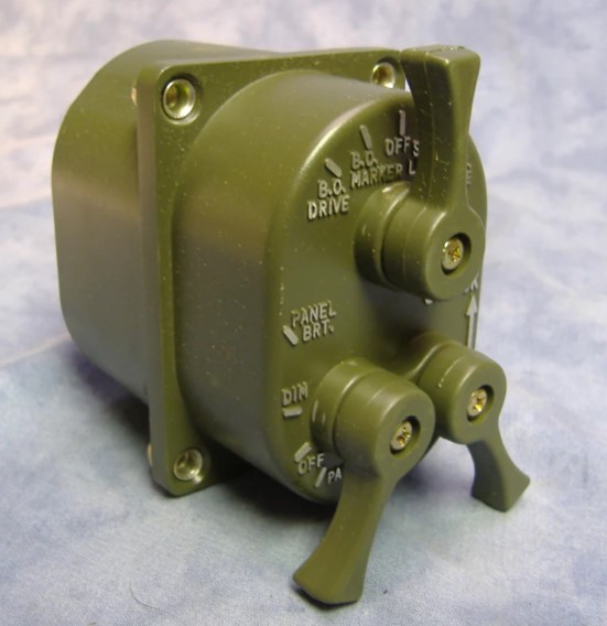
From Big Mikes Motor Pool at https://www.bigmikesmotorpool.com/products/three-lever-light-switch-ms51113-1
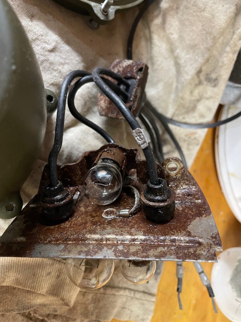
The connector itself is unlikely to be bad unless its damaged, if you are doing a rewire it is likely that this part won’t need replaced, just redone. If you get a replacement you will have to wire it anyway. In my truck the wire insulation was crumbling in places so I am doing a complete rewire, including this assembly.
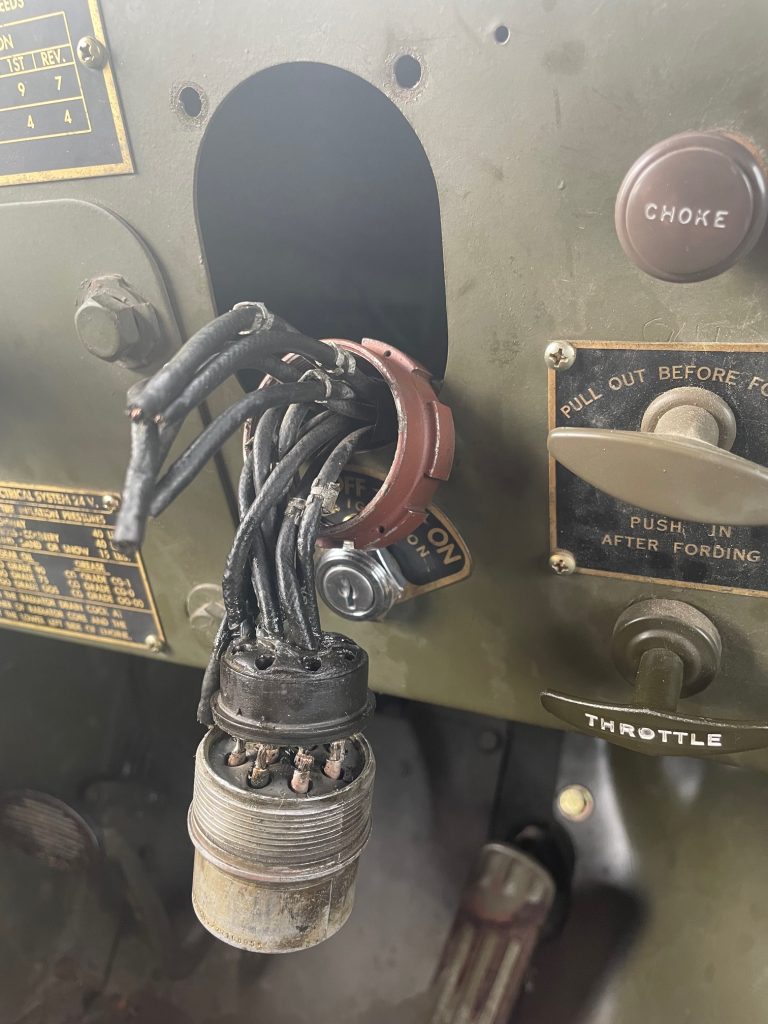
Use silicone grease and gently nudge the protective rubber shell over the wires. It will take some patience as you don’t want to damage the rubber so it can be reused assuming its still serviceable.
Once cut free, you can tin the solder cups. Lead free solder was not working for me, I had to use lead solder. The cups have to be clean and clear, I heated each cup with iron at highest heat setting and tapped the assembly on the worktable to dump the solder in each cup. I used a torx screwdriver to ream out each cup to have a clean surface as used flux and other junk accumulated in these cups.
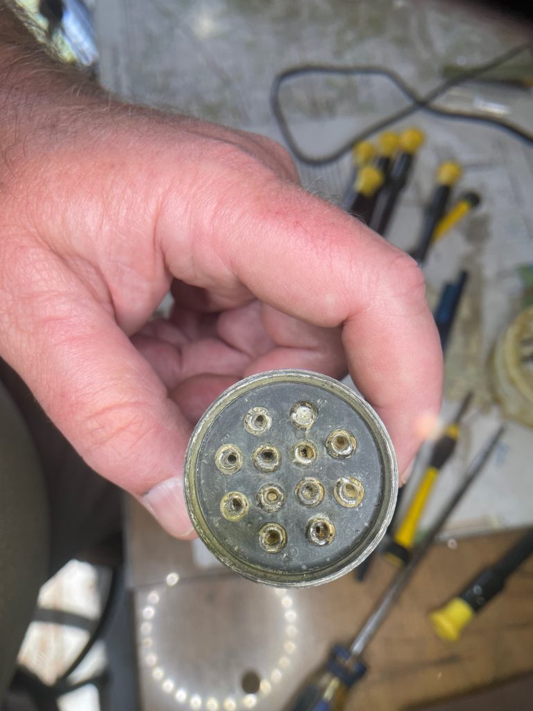
Before soldering, the wires must be combed and in the correct order or it will tangle up and the protective rubber shell won’t fit over the wires as it should. All the parts should be inline as it will be when it comes together to prevent not being able to get it assembled when complete. Juggling the wire order while also trying to work in the tiny spaces is a challenge. Wiring from the inside of the assembly and working your way to the outside ring helps a bit with the cramped space.
Tin the wire, if using the military type 14 gauge M13486/1-5 wire (Prestolite is the maker of the wire I have), it will take high heat and lead solder to tin this wire. It should have a coating of solder without blobbing, and should fit into the cup on the connector. Flux well and heat the connection, when you feel it drop down into the cup, and is filled with solder, the connection is done. It takes some time and a lot of heat to get the wire to drop in the cup. I used denatured alcohol (sold as alcohol fuel at home depot) and qtips to clean up flux.
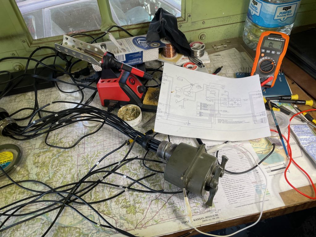
When I finished soldering my connections, I tested the assembly by checking continuity with a three lever switch connected. One end of the multimeter on the power feed line (circuit 15) and switching the three lever switches between modes to see if there was good connection. I used the standard military circuit list called “7070301 Circuit Numbers” an example of one can be found at https://jatonkam35s.com/DeuceTechnicalManuals/7070301_circuit_numbers_dolph.pdf. My wiring isn’t standard, but the closest diagram I could find was at https://wawii.com/images/M37%20Wiring%20Diagram%20-%20with%20Signal%20Stat%20900%20a.pdf
The metal wire tags and stamp set I found at https://www.nationalband.com/wrap-around-tag-m434363-1/ part or style number is M43436/3-1. The 1/8th in stamp size fits on the tag and appears to be what was used on the original. The stamp set is found at https://www.nationalband.com/fasteners-accessories/ as style 1571. The sales rep told me you can wrap these with finger pressure and I didn’t really believe it, but its true, they bend into shape fairly easily, but once on are sturdy. When stamping the numbers I am using a light tap with a light hammer, it does not take much to imprint the numbers on the tag.
The opposite side of this assembly will be Packard rubber shell connectors so the assembly can be serviced later if needed.
I don’t intend to crack open the 3 lever switch itself, but I did find an article where someone did and I found it interesting to see how this switch works – http://pages.suddenlink.net/randygar/switch/switch.html