We didn’t make a whole lot of contacts, but I did have many visitors. Some visitors even got on the radio and made contacts. I used the DX Commander antenna and remembered what a great antenna it is. The Hamsticks from Shark Antennas are very convenient and work well, but that DX Commander really gets good reception and perhaps my reach was a little better. I fixed some issues I had with antenna connectors which let me use the DX Commander this time and tested the two antenna types side by side. Its been a couple years since I have drug it out, but I am happy to have it back.
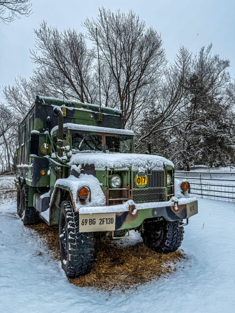
4 bulkhead connectors are just above the drivers cab, but the two lower ones are difficult to get too, 90 degree angle connectors solved this issue. The two upper connectors are for a VHF whip and one hamsitck chosen from the set of hamstick whips.
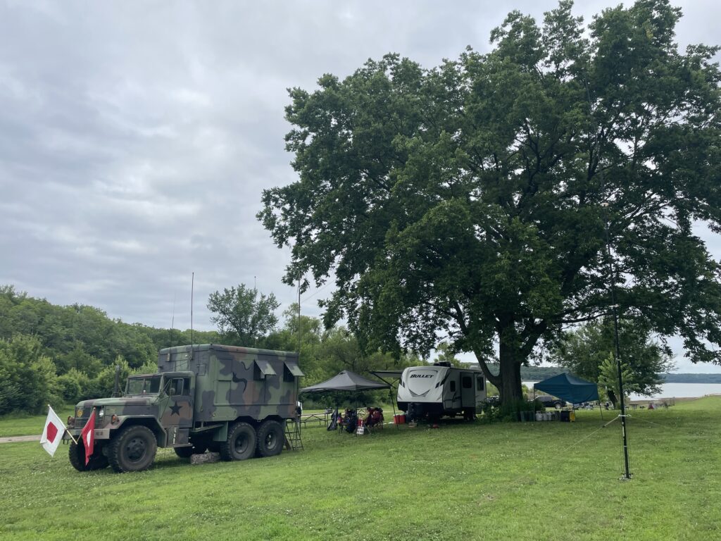
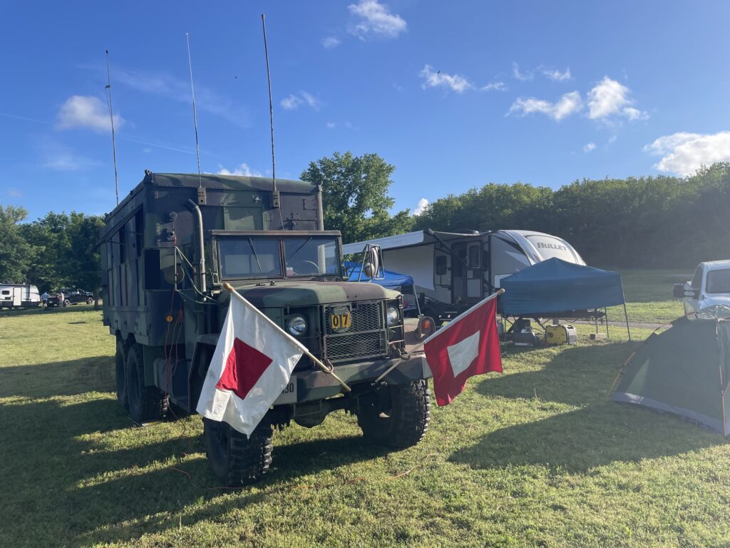
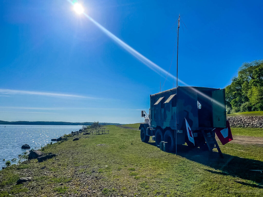
My full antenna setup is the 4 forward bulkhead connectors feeding two whips, the discone at the rear of the truck, and one external antenna which will normally be the DX Commander.
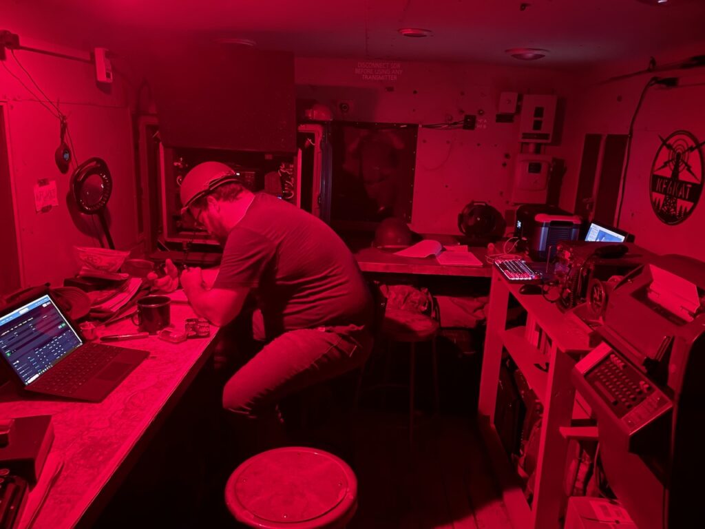
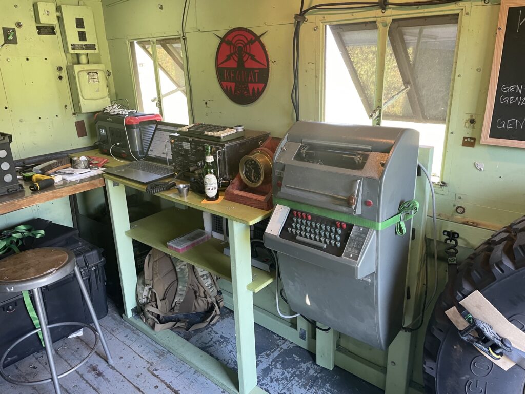
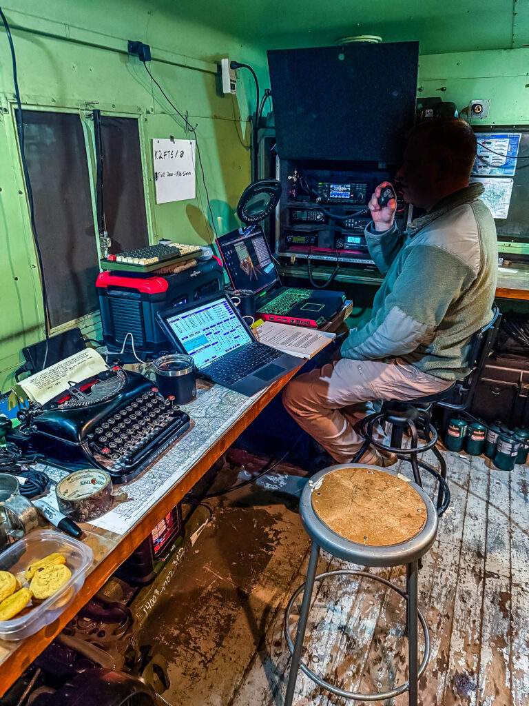
I am fairly happy with the interior, the work I have done makes setup and tear down much easier and the layout works with up to three people doing various tasks – one radio operator, one logging person, and typer/call sign lookup person. Digital work is done by having the operator turn around to the computer opposite of the radios to send and receive messages from it.
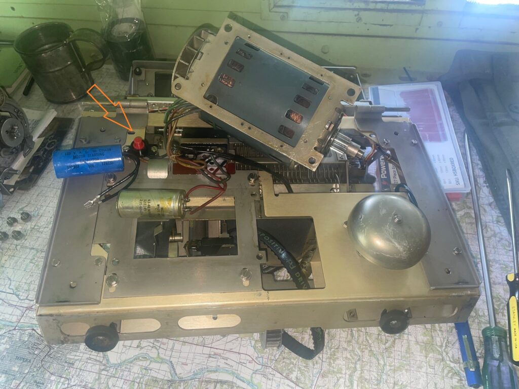
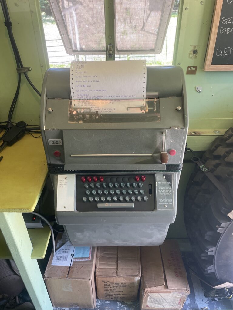
If your Model 28 Teletype does not start at all, the lights come on but there is no movement, it may be as simple as pressing the reset button. This is a Model 28 Wall mount with a unique motor layout, so yours may be elsewhere, but it will be near the motor itself.
Unfortunately, they placed this reset button in a very inconvenient location, so reaching it will require some disassembly.
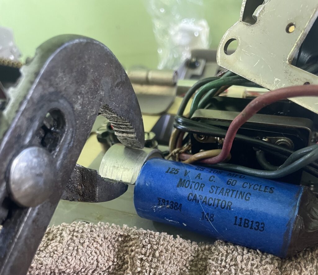
If your Model 28 frequently requires this reset, or experiences motor bounce or weak start then it may be the starting capacitor. If you turn on the machine and you can observe the motor shaft bouncing back and forth, but never making a complete revolution is describing what I am calling motor bounce. A weak start is where the motor can make a full revolution, but it takes awhile to get there then spins up to speed slowly is what I am calling a weak start.
Capacitors do have a life span, and while these machines are incredibly durable, as evidenced by this machine still working, capacitors can wear out over time. The startup capacitor gives the heavy motor a kick to get it going from idle, and in normal operation the Model 28 will instantly spin up from idle when turning it on.
Teletype Bulletin 295B or 570-220-100TC-6503 have descriptions and diagrams of various Model 28 Teletype variants (found at http://www.navy-radio.com), but Bulletin 295B has some part numbers for the startup capacitor. You may find these either by asking at the Greenkeys mailing list, or from Mr RTTY http://johnwhitney.com/misc/paul-rtty.htm.
On my machine I found it was easiest to move the motor mount to get access to the startup capacitor. Not difficult, it was just 4 large machine screws. I did have to slip the belt off by removing tension on the belt which requires loosening three tensioning screws.
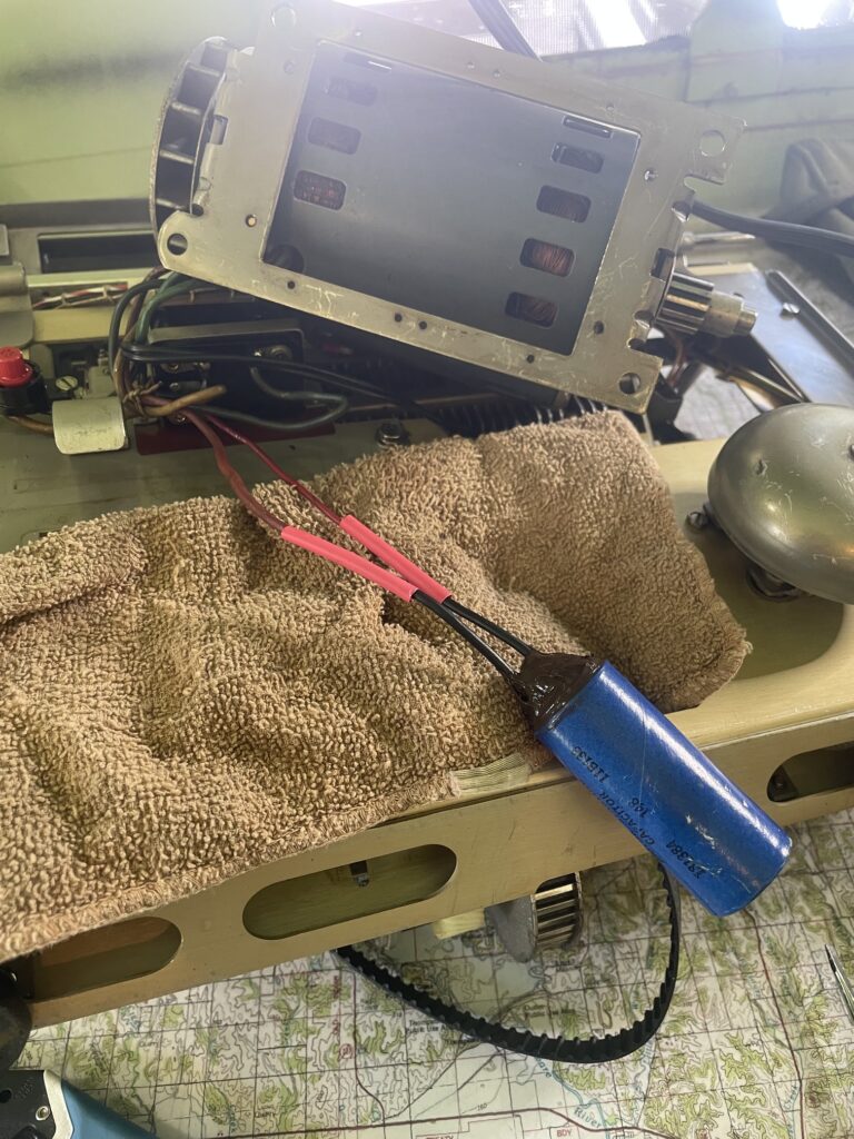
The startup capacitor is friction fit in place, I found channel locks worked to (gently) lift the clamp so the old capacitor can be removed and the new one put in place.
The replacement capacitor had beautifully attached spade terminals, but I opted to clip them off since I want no possibility of those terminals touching something and shorting. I opted to join the wires with solder and shrink tube them together. There are no orientation markings on the old or new capacitor, and it is AC, so orientation is not important from what I am reading. I put some silicone on the leads end of the capacitor to give the somewhat delicate connections some reinforcement and to prevent anything from shorting the capacitor out.
After replacing the capacitor I have eliminated my machines tendency to trip the cutoff forcing me to reset it often, and the motor no longer tends to bounce more often than not on startup. Startup is nearly instant and strong, which is what I have found to be normal in viewing videos of other peoples Model 28 Teletypes.
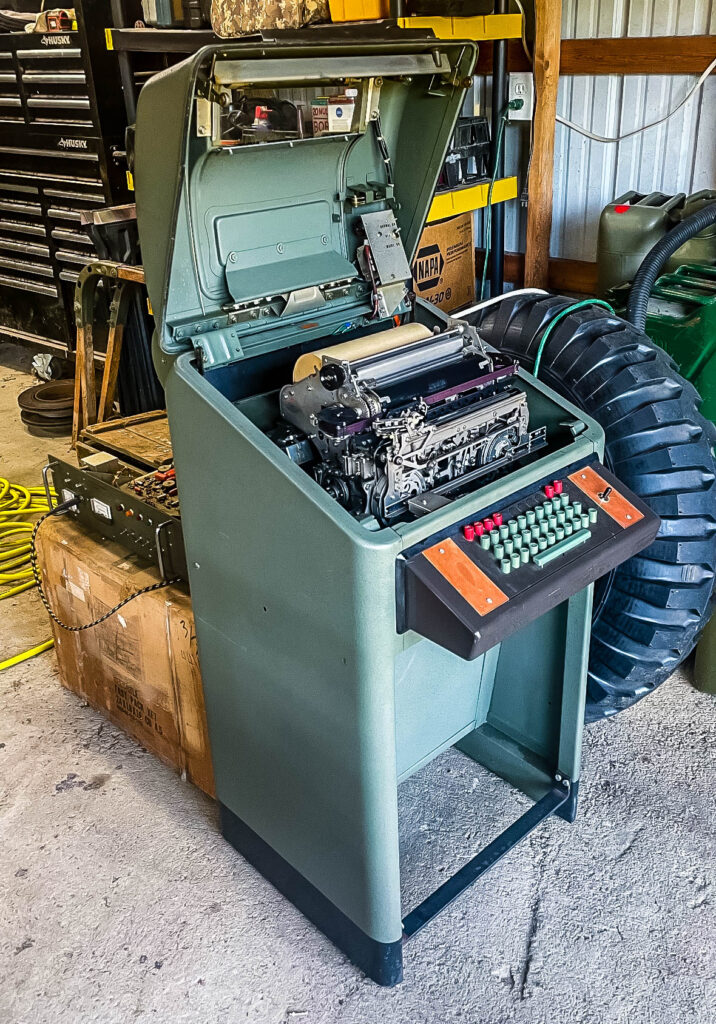
Got my hands on what I have been after, an Army Signal Corps teletype with this example being the Kleinschmidt TT-4C which will fit perfectly in my truck setup and be usable on the air.
Now begins the slow process of attempting to figure out how it works without breaking it. I did get a couple of tips from the greenkeys list – GreenKeys Info Page – about initial steps. One particularly helpful set of startup ideas came from a museum curator which I was happy to get. Assuming I get this up and going, ill post some procedures since there are quite a few tricky parts to this machine.
Did Winter Field Day with Flag and Torch Society for 2026 – Flag and Torch Society. It was alot more fun to do with a group and I hope to do this again. This Winter Field Day happened to fall right in a winter storm, and while this made it more challenging, it probably was good to exercise the setup in adverse conditions. I did learn quite a bit so I’m glad I was able to participate.
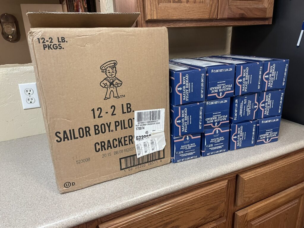
Pilot bread is often stocked in Alaska, but for people outside of Alaska there really isn’t a place to get it other than Span Elite – Alaska’s Premier Online Grocer – Span Elite. They do ship to the rest of the US if you are interested in pilot bread. Pilot bread is a shelf stable “hardtack” but does not have the extreme hardness of historical hardtack. Its something like a saltine cracker, without the salt. I like this for camping and its wise to have something on hand for power outages or getting snowed in.
We were stuck in our home about a decade ago from snow, and I got some pilot bread after that snow to be better prepared for such events. The power went out for a few days and we couldn’t cook very well, despite having a wood burning stove. We haven’t had this extensive of a snow in since then, but I have dipped into the stash over the years for camping trips since I am actually quite fond of these crackers.
Checking in on our stash I realized these are a decade old at this point. I tried some and found they are still good, a tiny bit stale, but no surprise give how old they are. We re packaged them at the time in vacuum seal bags and that seems to have preserved them well. We may try some of those freshness packets (the ‘do not eat’ things you find in jerky and such) in packaging this time to extend them better, but they seemed to do well just vacuum sealed.
These aren’t super expensive ($100ish for 24lb), but I think they are worth the little extra money given how durable they are. If you have ever wondered if pilot bread is a good thing to have on hand for emergencies, I would recommend them. They are about 100ish calories per cracker and if you like saltines, you will like these.
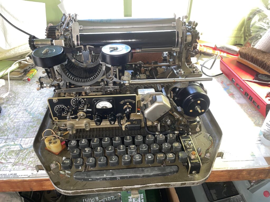
I found a beautifully maintained Model 28 with fascinating features. It has a paper winder, switch on the keyboard to activate a radio key for transmit, and it included a terminal unit. It is geared for 60 words a minute so this is what I would need to participate in on air teletype contacts. Not having been confronted with the need to connect to a radio for transmit with the other teletype, ill have to figure this part out. I have listened to RTTY on the air, but never attempted to transmit on it and the details of this are not obvious. A place to start seems reoccurring RTTY nets at 3905 Century Club, figure out reception, then work on transmit.
This machine will be a great addition to the M35a2 setup, but ill have to make some choices on layout, ill likely be able to fit it with some shuffling and some way to shield it from shock while moving.
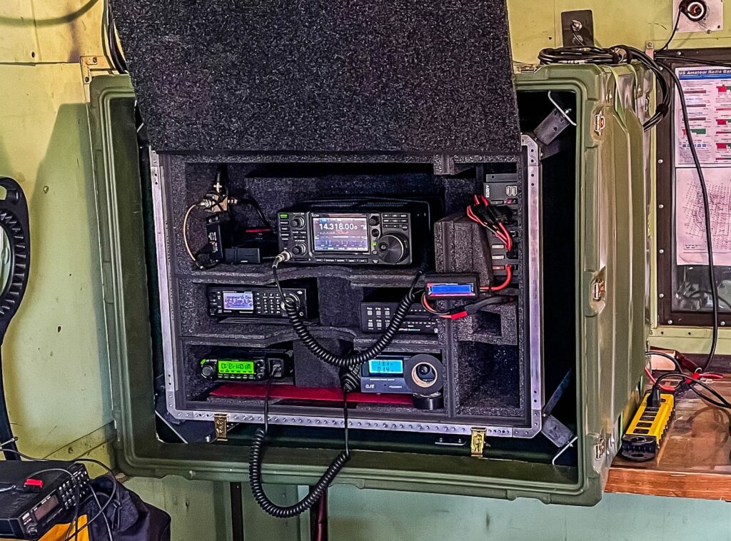
I have seen a few people recommend a Raspberry Pi as a ham radio computer/controller, notably Off Grid Ham Radio OH8STN, at least in the past. Having incorporated a Raspberry Pi4 in my setup for a few years, I find they are well suited for this.
Raspberry Pi in the top left corner next to IC7300
My setup is a Pi4, powered by a large 12v battery (Duracell deep cycle gel type) connected to a 12v to USB-C (60w) device from Coolgear. I use the device from Coolgear since standard USB power seems to be to little to drive the Pi, it frequently indicates low power unless I use the Coolgear device which provides higher wattage. The battery will keep the Pi alive for at least a couple weeks and can be charged by solar or using a 12v charger. The Pi gets time from a u-Blox7 USB GPS receiver, since Internet access is not usually available at places I camp and time, at least the seconds portion, is important to digital modes. The GPS receiver is in a PVC pipe outside the truck and can be seen at the top right, the GPS does not work in the metal enclosed truck. This Pi connects to the IC7300 and I have rig control and access to digital modes from the Pi. I use VNC (Virtual Network Computing) to then operate the Pi from a regular computer, or even old IPads. Since the Pi can operate as a WiFi hotspot of sorts, albeit without internet, I can VNC from anywhere in the vicinity, even a cot in the tent away from the radio.
The advantage of using a Pi is its very low power draw allows sessions to be sustained without interruption for days, much longer than I would ever operate POTA. If my display computer runs out of battery, I can charge it without losing track of received messages. I generally just let the Pi run for the entire trip without having to worry about it, ill just VNC whenever I want to use it. The Pi is also incredibly inexpensive; I got a kit from Vilros for about 60ish dollars that came with a very nice metal case.
A disadvantage of the Pi is that it isn’t a very fast computer, but it is just fine for handling digital modes. A variety of logging software I have tried lags though, enough to hinder fast moving activations. I generally log on a regular computer to log contacts. I have been using HAMRS for logging.
My preferred digital mode is JS8 using the software JS8Call. I do enjoy voice contacts, but voice is a bit difficult for me with my howitzer hammered hearing. Digital modes allow me to make contacts without having to depend on my ears. JS8Call uses signaling that is stated to be effective even at low signal levels, and this seems to be true in my experience. I like the idea of being able to pick up even faint stations. JS8 isn’t a very fast protocol, and it isn’t a very good choice for racking up log entries, but usually I am not after numbers for POTA or contests anyway, I am more focused on what can I get my equipment to do. For most POTA trips or contests I’ll try to log at least a handful of JS8 log entries.
My Method of setting up a Pi as a radio controller
Install the Pi Operating System
Use the AmRRON setup script to install radio specific applications
Resolve problems with JS8Call
Connect the radio using FLRig, resolve audio connections and audio levels for JS8Call
Set up time with GPS and Chrony
Add final add on applications
Installing the Pi OS (Bookworm)
Any computer that is updated over time, adding and removing software, gathers some unwanted stuff laying about. Every year or two, I start with a fresh install of the current Pi software, beginning with the Raspberry Pi Imager. I have a computer monitor that I use to get the Pi off the ground after first boot, VNC is not turned on by default. You have to turn on VNC using raspi-config or using the “Raspberry Pi Configuration” under preferences after you boot up. Turn on SSH as well.
Raspberry Pi wants you to use the “Raspberry Pi Connect” application, but it requires a login with it’s service and gives global access to your Pi, which I don’t really want or need for this application. RealVNC Viewer works to access a Pi with VNC active. If you have trouble getting a VNC session to display, try other video modes using the “Screen Configuration” app under preferences in the Pi GUI. From here, do a standard update; the Pi has an icon in the top right indicating updates are available and choosing to install updates takes care of this process for you. After this the base OS is ready. It may be a good time to backup what is completed so far using the SDCard copier under accessories, you will need a second micro SD Card to make this backup.
I have found that while RealVNC server (the previous default VNC server on the Pi) was very stable, the new wayvnc server that is stock with the Pi sometimes flakes out. To restart it, SSH (PuTTY is free) to your PI and use:
run – sudo systemctl restart wayvnc
Install Radio specific applications with AmRRON setup scripts
To then install the software, there is a tool created by AmRRON that largely automates the installation process. You can find this tool at AmRRON setup-scripts where you can also find a very helpful guide on using this tool. I haven’t used all the applications it installs, but I am primarily interested in FLRIG, as the interface to the radio; JS8Call, as the digital mode software I use most often; and Fldigi, a program that gives access to a large number of various digital modes. I also occasionally use WSJT-X to see what I can reach given my equipment and location. I do need to make time to explore the other tools it installs, such as the packet radio applications. This install script take quite awhile to run, so be prepared for an hour or two of watching compile screens. This set of scripts also states it is written specifically for Linux Mint, so some software needs help, specifically JS8Call more often than not.
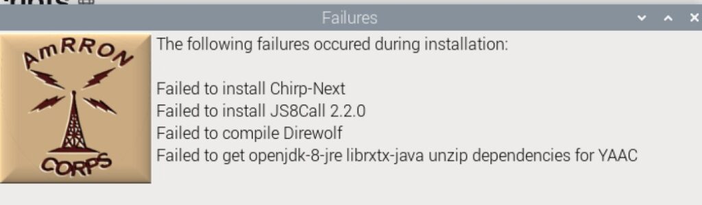
Some software fails, just try reinstalling, except JS8Call that needs extra help
For a variety of reasons, some installations may fail. Note them and reattempt them. I have found that the servers where this software comes from have temporary problems which is the most common problem, except JS8Call. With the exception of JS8Call, all the failed applications in the screenshot above worked on a retry. JS8Call often has issues with installing on the Pi OS, and every time it is software dependency that is the cause.
Resolve problems installing JS8Call
The official JS8Call install instructions to build JS8Call from source code located at js8call/INSTALL at main · js8call/js8call · GitHub also fails due to unmet dependencies, but this may change over time so it is worth trying.
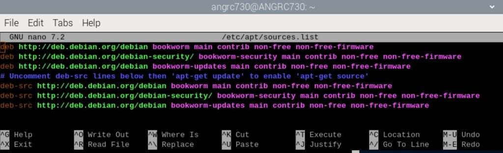
uncomment (remove the # symbol) from the last lines beginning with #deb-src like below. Use control-o to write the file and control-z to exit. The article references the previous version, “bullseye” but the Pi is (currently) on “bookworm”. This change permits the Pi to access expanded libraries of software
run – sudo apt update
run – sudo apt upgrade -y
From here, I tried the compilation method detailed in the article, which does work and installs version 2.1. You can skip the Hamlib sections as the AmRRON script will have already installed this. I would rather have the more recent version vs 2.1, however. I did find a method at How do I install a .deb file via the command line? to attempt the version currently listed at files.js8call.com/latest.html, which is version 2.2. It also fails dependencies, but using the following:
run – sudo apt-get install -f
run – sudo dpkg -i js8call_2.2.0_armhf.deb (after downloading this .deb file, and using cd to go to the directory its located in. Change the file name if the version number changes)
This finally worked for version 2.2 on a Raspberry Pi Bookworm. The packages will catch up eventually, but Raspberry Pi often seems to have difficulty with standard JS8Call install packages when the Pi bumps versions. I have more often than not had to spend significant time getting it installed, but with JS8Call being my favorite digital mode, it is worth the hassle.
Setting up FLRig and audio levels
I found setting the audio levels when I first started digital modes very difficult. It took me quite a while to figure out why I couldn’t receive, and when I finally could receive, why I couldn’t be heard.
FLRig is a great program that acts as an intermediary between your radio and the various software that accesses your radio, at least for ‘rig control’.
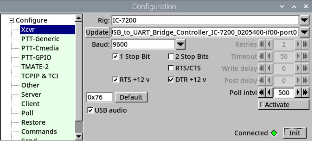
After connecting the radio to the Pi with USB (or whatever your radio model uses) you can run FLRig and see if you can get connected to it. The documentation for FLRig is flrig_help: IC-7300 Setup, and there are pages for various radios. I am using an IC7200 in this example, but the setup for a 7300 is similar, you may have to mess with Baud. Use a faster baud if it works for you:
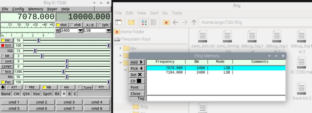
You can also have a directory of frequencies and modes saved to quickly jump between these. When initially setting at a POTA campsite I normally monitor 2.5, 5, 10, 15, 20 Mhz from Radio Station WWV | NIST to get a sense of what bands might be doing well and to get audio feedback that my antenna and radio are working. Having these frequencies saved in FLRig makes it easy to switch between these. This directory of frequencies is per radio and the file that contains these frequencies often gets eaten so I have made a habit of saving this file elsewhere. It is located in the Pi’s home directory /home/.flrig by default and the file ends in .mat. I have an IC7200 and IC7300 so FLRig has a different .mat file per radio, but I can simply paste the contents of one radio’s .mat file into another. the .mat file wont be created until you save a random frequency using the memory menu and then exit FLRig like below:
Below is an example .mat file (for specifically an IC7200):
You may have to massage this file if moving it from one radio to another, which is easier than recreating it from scratch for each radio. The (sparse) documentation is here flrig_help: Memory Dialog, but the basic jist is the first number is the frequency, the second is a radio specific mode, and the third is a radio specific bandwidth. I just copy this file from one radio to another, save an example, eg a data mode, then use the data from it to modify the rest of the list. I keep a large list of various frequencies, voice and data, so I can easily switch from one to another with FLRig.
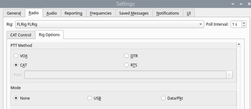
Once you get FLRig working, you can tell its working if you tune the radio and the FLRig display matches the radio, you can start working on the audio.
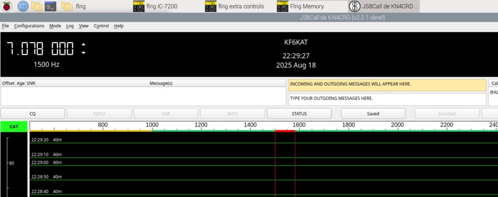
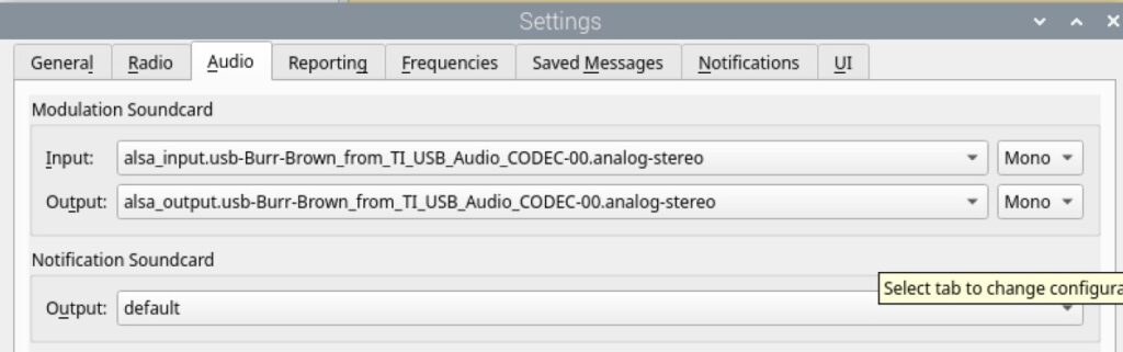
When you first run a digital mode software, in the above example, JS8Call, it will not display an audio waterfall. You have to figure out what input and output audio source to use. For a Pi and 7200/7300 combo it seems to consistently be:
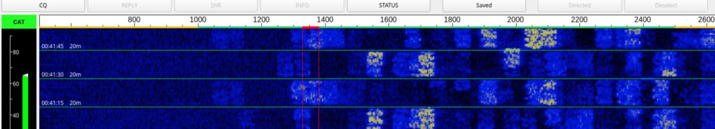
If the audio receive is working you will see an audio waterfall:
For the next part – the transmit, keep your power low and find a quiet spot on the airwaves. You will have to transmit to find the optimal output audio level. The AmRRON install script offers PulseAudio as the Pi audio levels application and I have found it to be straightforward. You will need to pay attention to the output power of your radio, which should be greater than none and close to the power level you selected.
You also need to pay attention to ALC (automatic level control). The summary of the ALC feature of some radios will attempt to compensate for being overdriven (to much audio input) and this distorts your signal and potentially signals nearby. A good article discussing this can be found at Clean Up Your Act! Proper digital mode level adjustment in Windows 10 – West Mountain Radio. Although it covers Windows, the concepts will be the same for the Pi and PulseAudio.
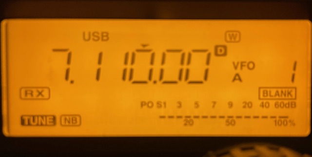
For an IC7200/7300, and other radios I assume, make sure you are set (on the radio) in a digital mode. The “D” to the right of the frequency indicates the 7200 is in a digital mode.
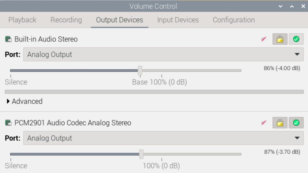
Start with a lower output using PulseAudio:
Use the SNR or CQ to test the output – use halt after you get a result:
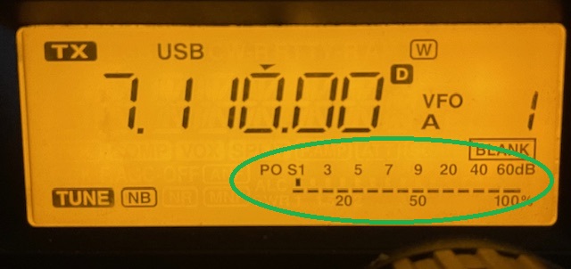
If your audio from the Pi is driving the radio, you will get power out on the PO (power out) meter:
I’m using very low power to not interfere with other stations
If you aren’t matching the output you selected on the radio with what is actually being transmitted, increase the volume in PulseAudio until you are. Eg if you selected to output 20 watts, you should be getting at or close to 20% on the PO meter.
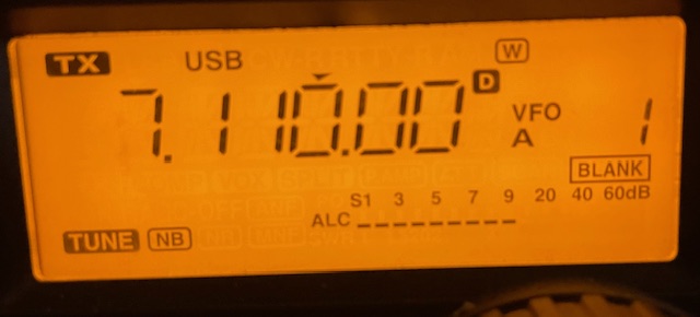
Next is ALC, on the IC7200 you can long press the “ANF METER” (top right) button to select the various meter modes.
With your Pi audio driving the radios transmit, keyed up using the CQ or SNR buttons in JS8Call observe the ALC meter. Ideally, it will show nothing, but it can safely bounce on the first notch:
This is an overview covering specifically the Pi and a 7200. For a more detailed document see JS8Call-Guide.pdf, a high-quality reference from the author of the JS8Call software, Jordan Sherer KN4CRD. There is also a video featuring the author explaining, setting up, and using JS8 at JS8Call Setup and Demonstration by Jordan, KN4CRD
Time, at least seconds, is important to JS8Call as it frames all its signals in intervals. The Pi does not have an internal clock and will drift wildly if you don’t give it time from somewhere. By default, the Pi OS assumes you have internet access, and it gets time from NTP over the internet. If you don’t have access to the Internet to get the Pi time, you will have to set it fairly precisely manually or use a GPS to get time. There are also hardware clocks that you can get for the Pi, but I have not tried them.
A GPS Device and Chrony, a Network Time Protocol (NTP) client
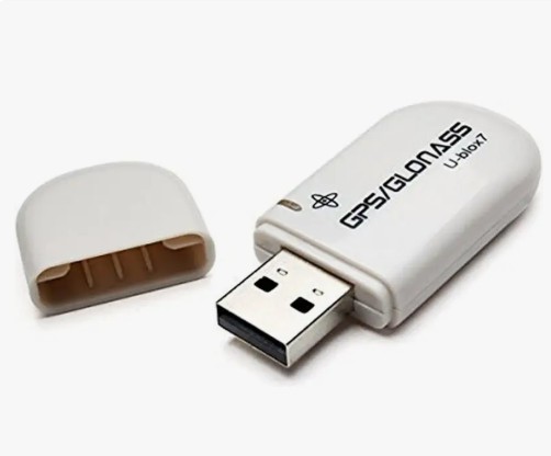
I am using the Ublox7 USB GPS devices. They are very inexpensive, and I haven’t had one fail in the last several years. Since it is USB, I can run the GPS device outside of my vehicle, which is critical since the GPS signal is weak. Any GPS device that can connect to the Pi should work for time, but ill detail my setup.
The first challenge is figuring out what port name is given to your GPS. If it is USB, I have used this method:
sudo apt install gpsd gpsd-clients chrony
Plug in the UPS GPS
Use gedit or some other text editor to create a script, I called mine usbfind.sh
Run – gedit usbfind.sh
Paste the below script into this new file (this suggestion found at Stack Exchange)
#!/bin/bash

for sysdevpath in $(find /sys/bus/usb/devices/usb*/ -name dev); do
    (
        syspath="${sysdevpath%/dev}"
        devname="$(udevadm info -q name -p $syspath)"
        [[ "$devname" == "bus/"* ]] && exit
        eval "$(udevadm info -q property --export -p $syspath)"
        [[ -z "$ID_SERIAL" ]] && exit
        echo "/dev/$devname - $ID_SERIAL"
    )
done
run – chmod +x usbfind.sh (to permit this new script to run)
run – ./usbfind.sh
In my case the GPS was – /dev/ttyACM0 – u-blox_AG_-www.u-blox.com_u-blox_7-_GPS_GNSS_Receiver, the important part being /dev/ttyACM0
run – sudo gedit /etc/default/gpsd
# Devices gpsd should collect to at boot time.
DEVICES="/dev/ttyACM0"
# They need to be read/writeable, either by user gpsd or the group dialout.
# Other options you want to pass to gpsd
GPSD_OPTIONS="-n"

# Automatically hot add/remove USB GPS devices via gpsdctl
USBAUTO="true"

START_DAEMON="true"
run – sudo usermod -a -G dialout *yourusername* (add your username to the group dialout, change *yourusername* to whatever your username is)
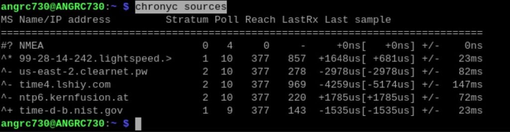
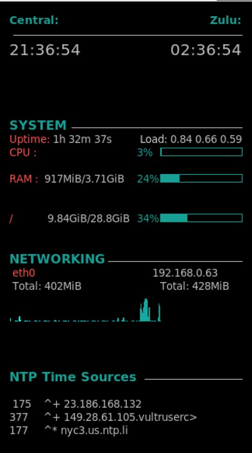
+ indicates acceptable sources which are combined with the selected source.
– indicates acceptable sources which are excluded by the combining algorithm.
? indicates sources to which connectivity has been lost or whose packets do not pass all tests. It is also shown at start-up, until at least 3 samples have been gathered from it.
x indicates a clock which chronyd thinks is a falseticker (i.e. its time is inconsistent with a majority of other sources).
~ indicates a source whose time appears to have too much variability.
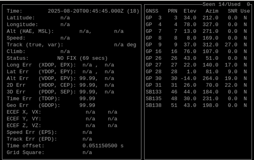
run – cgps (this will show what satellites are being tracked and signal strength of those. use ctrl-c to exit)
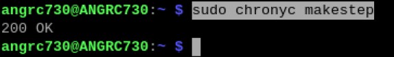
run – sudo chronyc makestep (this tells chrony to adjust the time in a bigger step. I often have to run this many (many many) times to get the clock correct if the Pi has been turned off)
Note – digging into this, I found chrony – chrony.conf(5) documentation on the configuration of chrony. The item of interest is the makestep configuration line there. One concept at play is slewing – time software avoids making large time jumps since this has bad side effects on normal systems (reference – NTP and Slewing). A potential solution would be to set the chrony.conf makestep option allow several more large time jumps rather than the default 3. Since the Pi does not have a clock, its time will always be wildly off when it first turns on and has no internet.
Conky, a system monitor and information display
The AmRRON script includes Conky, which displays information about the system and other things that you include. I modified time to show my local time zone, and most importantly, where I am getting time from. If it is my GPS, it will show NEMA as a time source.
The AmRRON install script will not autoload conky on startup on the Pi. To do this on Bookworm add a file in /etc/xdg/autostart with the following contents
Web server and mediawiki as a notes/documentation place
One practice I have done is installed a webserver and mediawiki to keep notes on my items, link things like user manual .pdf, and whatever else I want. This isn’t needed to operate a Pi as a radio controller, but it is handy. I may cover this topic at a later date since I find having a wiki useful.
Summary – Final dimensions as 10″ H, 9″ W, 6″ D. The two critical elements are that the two halves fall equally when opened to provide a stable base for the clock to sit when in use, and that the box hinge open without collision with the top of the clock face.
There are no officially documented blueprints for the construction of an M 1 or 2 Message Center Clock box (that I could find), although several pictures are available online. One such picture was available from the IMA website, which gave outside dimensions of the box as 9″ W x 4.5″ D x 10″ H (although these dimensions ended up not working on our example with the materials we had).
The box appears to be made of oak, based on the grain pattern and has no visible fastening on the outer surfaces to indicate nails or screws. This would suggest the construction is primarily held together with wood glue, with possible pegs or wedges acting as secondary support. Given that I do not have a box to deconstruct for reverse engineering, I cannot verify the exact construction. Tongue and groove reinforcement does not seem to be likely, however, given the lack of evidence on the internal edges.
When I constructed this box, I purchased readily available 3/4 inch oak boards from the local hardware store. These are listed online at Menards or Home Depot. It is not unlikely the genuine box was made from different thickness lumber, as modern dimensional lumber varies from historical dimensions due to construction conveniences (hence why a 2×4 is measured at 1.5 x 3.5). In any case, this thickness appears fairly appropriate to the pictures available. I purchased 10″ wide boards, which were 9.5″ dimensionally. This allowed for the correct width of the box without need for edge gluing. I Measured the clock and I had to be just under 6″ (around 5 7/8 inch or so), so this left roughly 1.5 inches in the internal area if two 3/4 width boards are factored in. When placed on its backboard, the depth of the clock was just under 4 inches. This would not have worked with the dimensions available on IMA, since two board thickness would have left only 3 inches on the internal area. So I opted to go with a 6 inches of depth for the box. This left final dimensions as 10″ H, 9″ W, 6″ D.
The box front and back boards were 7 1/2 inches wide, to allow for the side pieces to run to the front, as it looks in the photos. These were overcut to around 10.5 inches, to allow cutting width of the blade when making the opening. This was also true for the side pieces, which were 6 inches wide. The angle of the box cut was approximately 30 degrees. I first attempted a 45 degree angle but the height of the box appeared odd. 30 degrees allowed a good fit between the top and bottom portions of the box. To do this correctly, I made the cut from the back ends of the side pieces, marking the start of the cut at 5 inches, and setting the saw miter to 30 degrees. Doing these cuts at the same time prevents angle ambiguity in resetting the miter, which prevents headaches in future assembly. Cut both side pieces, then partially assemble the bottom portion with both front and back. Mark the area where the bottom of the angle meets the front piece and cut the front with a 30 degree angle on the blade. You can trim the excess wood from the top before final assembly. For the back piece, since there is a hinging mechanism, the angle would impede on opening, so make a straight cut at 5 inches. This should be verified with the dry assembly as well. The bottom and top caps can then be cut based on how the pieces fit together, or roughly 7 1/2 inches W x 4 1/2 inches. Test fit these pieces together, trim as needed, and glue or screw into place the pieces. I found pre-drilling and countersinking the holes are needed, as oak is prone to splitting. For a static display box glue might work, but if this used as a transit case, screws or dowls would be needed for durability. This example will be used as a transit case thus screws were used. This introduces the holes seen in the photo, which isn’t in the originals, so dowls may be an option if you want an unblemished example.
The next factor to determine was construction of the backboard itself. The wood edge around the clock looked to be around 1/4 inch, so I cut a roughly 6 1/2 W x 7 1/2 H slab. This allowed me to find the center of the semicircle by placing a compass where it met around the top and both sides of the boards. I scored a line to mark the edge of the semicircle and cut the circle out with multiple cuts on the table saw, finished with a belt sander to meet the line. This could also be done on a bandsaw or scroll saw, but I wanted to get cleaner edges. I placed the clock on the centerline of the board and roughly placed it where all edges looked equal. This allowed me to mark the top hole for the screw and pre-drill. This let the clock hang so I could mark the bottom two holes when it was partially installed. The backboard can then be fixed into place within the box by drilling two holes into the bottom of the box and running screws into it. Additional support can be provided by a screw in the front of the backboard, running through the back of the box. Just make sure it is a short enough screw that it does not penetrate through the back.
Stain and a layer or two of protective coating (I prefer Tung Oil), then you can install the hardware. Hardware itself is available at any hardware store, but mine came from Rockler.
Not a lot of activity, but did want to get the systems out and tested for the upcoming season, particularly June Field Day. It was nice to get back to the lake and operating after an idle winter.