The Army Signal basic course is generally designed for a track beginning in signal units. Some new lieutenants may find themselves assigned as an S6 in some other type of unit and there isn’t much opportunity to figure things out before finding themselves having to know things that really weren’t covered in training. Here are the habits I developed to ensure that me, my section, and my unit were prepared to communicate effectively.
- Find out what the unit is supposed to have
- Find out what the unit actually has
- Find out what the maintenance status of this stuff is
- Find out how the unit operates by doctrine and how communications are part of this
- Find out how the unit actually uses the equipment in operations
- Find the TMs, and any locally made documentation for systems
- Find out the capabilities of the equipment your unit is assigned
- Find out if there is any training time available that you can request for these systems
- Find out the training events of the unit and start planning for these 12-24 months out
Finding out what the unit is supposed to have should be fairly straightforward. Your S4 or supply Seargent should have access to print the Modified Table of Equipment (MTOE). The MTOE is the allocation of people and equipment for your unit and will list almost everything. Analyze this and extract communications equipment and to what section it belongs to. I found it useful to make a slide deck of sections and the equipment they have, with photographs of the equipment. Section leads stated they found this reference helpful when doing inventories particularly with little used equipment. This reference will have value for you so that you know exactly where equipment is supposed to go and who is responsible for it.
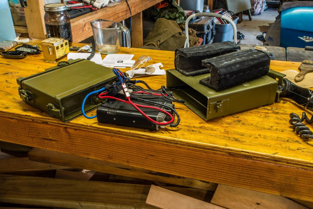
The unit may have communications equipment that are additional authorized items, or they have issued for some special purpose. Accounting for these and including them in your inventories will give you a complete picture of what the unit has (or should have). Some items are authorized for purchase based on unit priorities, such as power supplies for dismounted radios or special antennas, looking into these and seeing what is available would be a good use of time. One vendor is PTS Inc – Tactical Expeditionary Communications | Huntsville, AL | PTS, Inc. (pts-inc.com) which carries useful accessory items that the unit may want to buy. Your S4 will tell you the feasibility of this. In some cases, you may have equipment that is on your MTOE that has not been issued for a variety of reasons. Knowing what special non-MTOE items you have and what MTOE items you are short gives you the whole picture.
Finding the maintenance status is tougher to get a handle on. Your S4 can get you on the right track, but it will take some doing. Your supply Seargent can help you with the HQ unit, but the companies/batteries will have to provide info on their units. You won’t have tasking authority as the S6, but you can think through what information you need, think through what is realistic for an already busy unit to accomplish, and task units via your S3 (who does have tasking authority) to provide that information. Most communications equipment have periodic maintenance that needs to be deliberately managed, talk with your support facility to find out what needs this and how often. Having your equipment stuck in periodic maintenance when it is needed for training is a very bad situation. Look at your training calendar for 12-24 months out and request deliberate operator maintenance events and identify periodic maintenance opportunities so this is never a surprise to anyone.
Knowing your unit and its doctrine is very important. You cannot provide effective communications plans if you are unfamiliar with what your unit does on the battlefield and the terminology they use in operations. Ask your S3 to point you to the doctrinal publications for your unit – for example (cannon) artillery would be The Field Artillery Cannon Battery ATP 3-09.50 and The Field Artillery Cannon Battalion ATP 3-09.23.
Doctrine and what a unit actually does may be different to varying degrees. Participate in Military Decision Making Process (MDMP) meetings to fully understand operations even if communications does not come up directly. Knowing, in detail, an operation will give you insight how to best support with communications. You will be at a disadvantage if you opt to limit your participation. Ask questions at an appropriate time about items you aren’t following. Details about how the unit historically distributes communications security keys, how they establish communications nets, who is required to participate in what net, and similar items will help you to plan for these critical items, or if possible, improve these processes. Involve your NCOs and your S3 if you wish to modify something.
Finding TMs for equipment you have should be straightforward, if you don’t have them order them though your publications rep, or some are available on Army Publishing Directorate (APD) – https://armypubs.army.mil/. Prioritize your reading based on how important the system is in operations but read these TMs. You will have to understand the capabilities of the equipment if you are to make effective communications plans. The TMs likely will reveal little known capabilities that you can incorporate in your plans after you test them. Some systems are complex and TMs are inadequate to explain startup/shutdown and common tasks. In particular, information systems require this sort of locally made reference set. If they don’t exist, ask for them to be created. I would test these common task procedures by doing the task myself, if I could do the task, the documentation was acceptable. Having one or two soldiers that know everything and consequently are stressed when operations are in progress is undesirable, take note of things that consume their time and are easily made into a procedure document and spread the workload. IT people can sometimes be protective of their systems so you may have to insist, but the payoff will be your experienced soldiers can focus on advanced problems and newer soldiers can work on the routine tasks.
The TMs will introduce you to the capabilities of your equipment, but without testing, it is risky to offer a capability to the staff for an operation. Signal soldiers tend to enjoy testing new features so making a realistic testing plan and criteria for success is usually a fun challenge for them. Once you verify that a feature is reliable in a variety of conditions, you can offer these capabilities to the staff as options for an operation. Shorthand capabilities or ‘Planning Range’ (for radios) is a good way to express things to non-signal soldiers but exercise these things as experiments. For example, conducting a terrain analysis for an area then sending a team to verify a radio set works where you expect it too, and fails where you think it may can be a useful experiment as well as interesting training for soldiers.
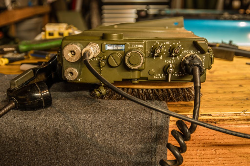
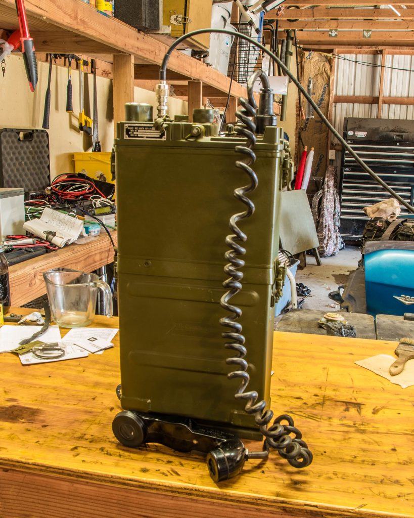
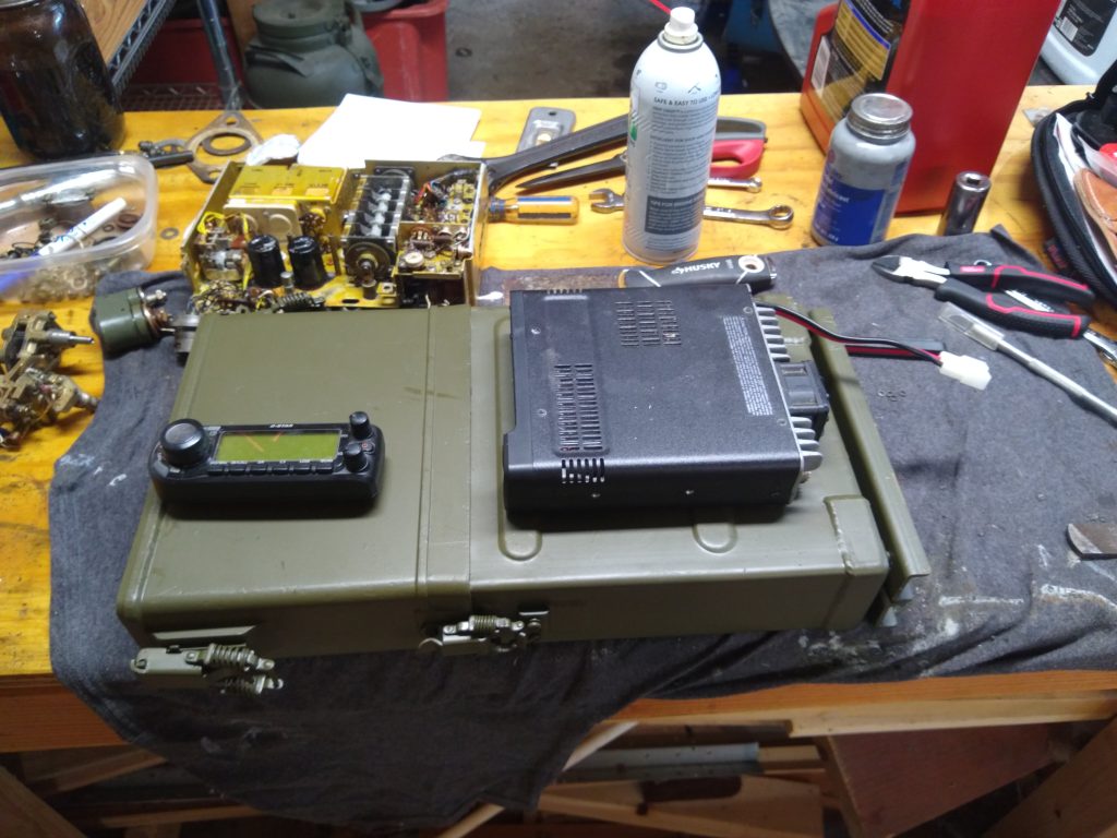
Look at your training calendar for opportunities to train the soldiers in your section primarily, and for opportunities to provide systems training to your unit in general. Your soldiers will generally enjoy unique training experiences that aren’t difficult to pull off. One example I was able to do was to send soldiers to a state park and set up an HF station so we could test some PRC-150 capabilities. This kind of thing is difficult to do ad hoc, but much easier if you get it formally scheduled. The HHB/HHC Commander is the starting point for these kinds of things, particularly if you want to involve the Battery/Company as a whole such as for training of loading radios or operator maintenance. Asking your Commo chief to make (or have made) some realistic class outlines and slides for various subjects that your section can present is useful and generally welcome for inclusion on the units training calendar.
Planning 12-24 months out gives you ample time to gather needed items for training events. Executing a good communications plan really takes some extensive groundwork to make work, you have to consider the large number of items from the antenna to the handmike. Comsec, batteries, cables, accessories, Annex H to the OPORD (and all of it’s contents), spares, and much more all have to be considered before an operation. Generally, during an operation is too late to get something, particularly if you go to a distant training area and going to home station is not feasible. I made a checklist for myself and insisted that my Commo chief had one as well of all the tasks and items we needed for an operation. If we found something missing, we added it to our checklists. Knowing what you will be expected to do well in advance gives sufficient time to order shortages, do maintenance on the critical items, and think through your plans in detail.
Knowing what equipment you have, what it can do, what its status is, and having a well thought out plan of how to use it will answer nearly all questions your Commander may have for you. Most non-signal people like straightforward, non technical, answers to questions so anticipate questions that you may be asked and how to answer these questions without diving into deep technical explanations. Having answers to the above items will increase your confidence and increase the confidence your Commander and staff will have in you.
Over the last 20 years the US Army has been fighting a counterinsurgency. Communications requirements for this is quite different than what the US Army may be facing in the future. Having been around since the 80s (Cold War era), I remember communications that favored mobility and rather complex communications security (eg SOIs with changing identifiers, frequently changing frequencies, etc). IT systems are most definitely not mobile, and while you will have to maintain and train with these items, do advocate for training with mobile systems like FM and HF from time to time. Try to anticipate how a unit might fight in a future conflict, and how you can adapt what you have to these environments. Anticipate what your potential enemies might do to disrupt your communications and what you could do in response.