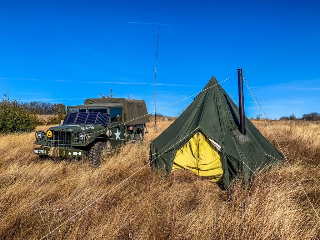
The weather couldn’t have been better with mid 40s in the daytime at Nebo State Fishing Lake, the location for our WFD22 camp. Amusingly, our first contact was someone very close to us, in the vicinity of Holton, KS and we likely picked them up on groundwave. We spent the majority of the time hunting people calling CQ, which slowed us down considerably, but we made around 80 contacts in this way. The M37 and trailer worked beautifully, fresh out of the garage after servicing all 6 wheel hubs. My two sons joined us for a bit and operated a couple contacts, and a fellow amateur operator joined for the whole trip.
WFD22 Camp at Nebo State Fishing Lake
My Duracell Gel lead acid batteries are shot so we had to use the generator (a Honda eu2200i) on this trip, but it did not cause interference and it is very quiet. I am pretty disappointed with the Duracells, I will have to try LiFePo (Lithium Iron Phosphate) batteries at some point. I am very happy with the generator, very easy to maintain and appears to be very reliable.
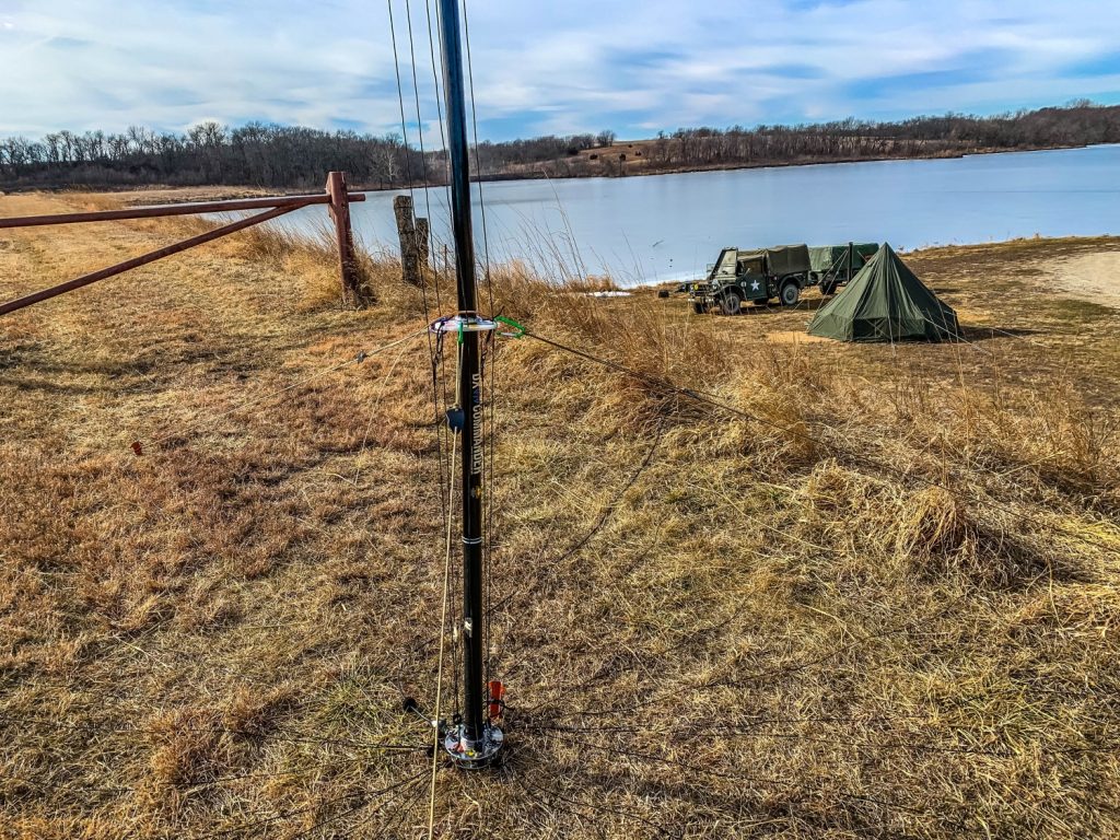
I also continue to be very happy with the DX Commander antenna, very easy to setup and it has proven to be rugged. I can easily set it up solo but having help of course is welcome. I cut the elements for data frequencies, so I did use a tuner for voice operations, but it didn’t seem to hurt performance.
DX Commander on the lake levy
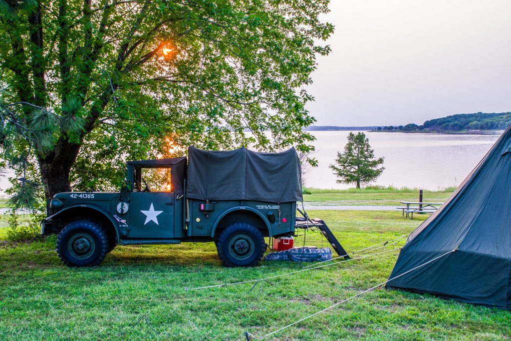
I really enjoy the WFD events and camping next to the frozen lake made for some beautiful scenery. Our score won’t be spectacular, but just getting out to a campsite and enjoying operating radio made the trip a lot of fun. Next field day, we will likely try incorporating another radio and antenna and try to double up our throughput, likely one data and one voice station.
One aspect of owning a military vehicle that I find fascinating is the parts you can get. Termed “New Old Stock”, meaning parts that have never been used, but are made several decades ago. I ordered a blackout headlight from Kaiser Willys (https://www.kaiserwillys.com) and received a part made in WWII – September 1944 assuming I am reading the stamp correctly.
Headlight from WWII
Of course I do not anticipate driving in blackout drive often or at all, but I do like for the truck systems to all be working if I can fix them.
When I was on active duty in the 80s-90s I often had to drive in blackout as the doctrine at the time was to operate exclusively at night as we had superiority in night vision. While that may have been true, not everyone had goggles and I spent the majority of time driving with the tiny of sliver of light these blackout headlights provide. While it works, it requires a great deal of attention and is fairly nerve racking to do. If you are hiding from aircraft, however, it is very effective at reducing how noticeable you are compared with normal headlights. It was the late 90s since I last saw any unit attempt convoy training at night on any large scale.
This blackout headlight style is an older type, and I am not sure what originally came with a factory M37, but the housing I have fits this type of lamp. The light that came with my truck was dim, and the unit was rusted through. These types of headlights are sealed units, the bulb cannot (easily) be replaced, the bulb and outer glass is press fit into the housing meaning the whole thing is replaced normally.
Since my original was rusted through and mostly ruined anyway, I forced the housing apart with a screwdriver and will see if I can adapt some 12v LED in the housing at some point later if the bulbs become difficult to get.
With the buck converter the lamp appears as bright as I remember them being from my time on active duty. The buck converter easily fits in the blackout headlight housing, even after putting some padding on it. If I ever have an occasion to use the blackout drive, it will at least be serviceable.
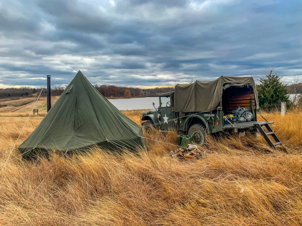
With Veterans Day weekend being a long weekend, it was a great opportunity to take the setup out and operating. I have a M101 trailer that came with the truck, but it is in the garage for bumper number painting and services to the hand brakes. The M37 held everything I needed, although the trailer is nice to have for bulk items like firewood and fuel cans, for this trip I had to get creative with the load plan.
Summarized inventory was Honda 2200i generator, 2 70ah Duracel Gel batteries, power distribution case, Icom IC7200 radio, DX Commander antenna, Raspberry Pi, and old Surface 3 for display.
I arrived in the afternoon and set up the tent with daylight, but by the time I got to the antenna it was dark. The DX commander is easy enough to deal with that I was able to get it set up in moonlight. I did modify it a bit, the longer elements, 80m and 40m, have clips attached to them so I don’t have to run them through the spacer plates. This isn’t perfected yet, but the basic idea is shock cord, shrink tubing, and a little glue to hold the clip in place. I set them to low so the elements move around too much, but improving the placement will make these nearly as good as intended design while greatly speeding setup and teardowwn. I also intend to add shock cord on the bottom of the element to reduce stress on the spade clips at the feed point. Once I get a final arrangement, I will detail this.
After getting setup, it was dark, so I listened to shortwave for a bit then got some sleep. In the morning, it was very cloudy so I had no solar. I decided to try a concept where I run the generator and connect a battery charger to the batteries and operate the radio. This did not work at all, at least with the charger I have. I do have an AC power supply, but having never needed it before, I generally don’t bring it. My daughter rescued my trip by delivering this power supply to my campsite. I have avoided using a generator previously as I have seen generators create interference on the radio set. Having no choice, I started the Honda 2200i and was pleasantly surprised to find it did not interfere at all. While I prefer using the solar when conditions are right, its nice to have an alternative for cloudy days and night operations. I have run this generator briefly before, but this is the first time I have used it for extended periods. It takes about a gallon of fuel for an 8 hour run, and appears to be very steady. It is also exceptionally quiet audibly. The generator was not specifically purchased for camping, but to power critical items during power outages at our home, but since it works well ill make this a regular item along with the AC power supply. I ended up using the generator for the entire trip.
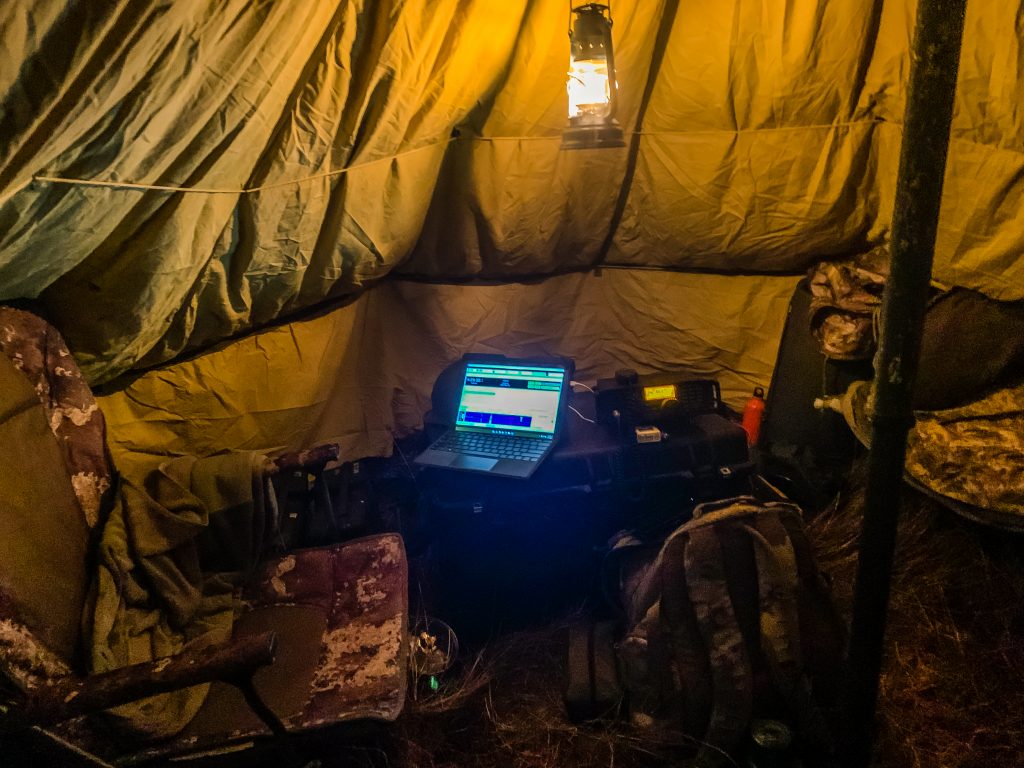
Radio Station
I used a program called HAMRS (https://www.hamrs.app/) for logging this trip. Previous trips I have used paper logs and transferred these to a log format to submit, but this is very tedious. I also likely did not format the logs correctly as it did not capture some elements like park to park contacts in these manual attempts. HAMRS was easy to use and I think I will keep using it. One thing I will change is where I am using it, I set it up on my Raspberry Pi and it could not keep up, which slowed the rate I could make contacts. When clicking ‘save’, it took about 20-30 seconds before I could type a new contact. In testing, using HAMRS on the display computer, a Surface 3, it responded right away so that is where I will run it in the future.
The M1950 stove is great, but is fussy with wood fires. I have to wake up every couple hours to feed it or the fire gets too low to restart easily. I have had problems with overheating, since the door of the stove does not seal well, but I have found that moving the fuel to the rear of the stove helps slow the fire down enough to be manageable. It is easy to cook on, however, this trip I had 15 bean soup, powdered eggs, and sausages for main meals, as well as a constant supply of coffee and tea. It is supposed to burn coal according to the TM, but anthracite coal wont burn in it as it is, so at some point I’ll have to see if I can get bitumen coal and try that.
I am very happy with my setup, the truck is fun to drive and my setup is, or nearly, complete. I think Lithium iron phosphate (LiFePO4) batteries would still be very nice as they cycle (discharge/charge) much better than lead acid, and being lighter would be nice. With winter nearing, I should be heading out more often for POTA trips and getting more contracts with my setup. This trip I made about 220 total contacts, much higher than my previous attempts.
This is likely overkill, but it is fun. The M37 is a military vehicle introduced in the 1950s to replace the WWII era WC 3/4 ton trucks. It is larger than a Jeep, smaller than a 2 1/2 ton, all my radio and camping equipment fits easily inside. I was able to take it to Lake Perry State Park for a parks on the air activity September 2021. I was looking at various recreational vehicles to move radio equipment, but none of those would be as interesting as this truck. The truck has many features that I will have to detail, particularly the antenna and mount that seems to tune from 30-50Mhz which is what I would expect for a military antenna.
This trip I was able to use the DX Commander antenna, which performed very well giving me 141 contacts in a weekend. With cooler weather nearing, I expect to get in the field more often since I find winter camping more comfortable than summer camping. I made some modifications to the antenna to speed up setup and tear down which I plan to detail soon.
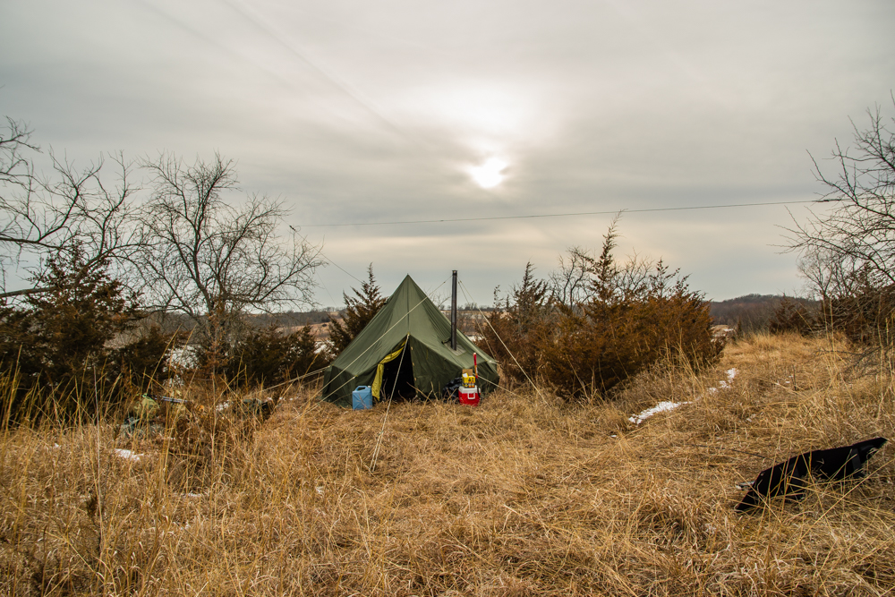
I have been looking forward to Winter Field Day and it was indeed a lot of fun. I picked Nebo Lake near Holton, KS since it is close and the facilities are well maintained. The terrain isn’t ideal for my current antenna, an offset dipole. Since I need tall trees to put this antenna up I had to decide to be on a hill where the trees were short, or near the lake shore where there are tall trees but my signal would be masked to the north. I ended up picking the hill, so as to not exclude northern potential contacts. The view was beautiful even though the weather was gloomy.
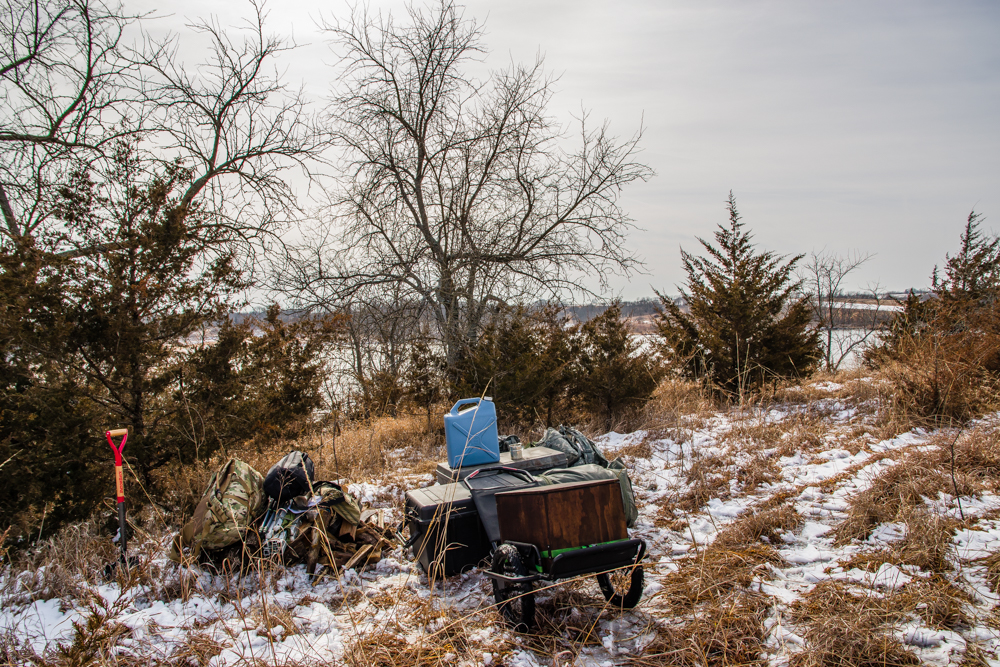
Getting set up
You can set up 24 hours prior to the event so I opted to do that so as not to be rushed. The hike in was about 100m, which isn’t far, but I really need better carts as moving the equipment was awkward. The photo above shows a grey box which has the stove and camp tools, the black box which is radio equipment, and the wood box which is the batteries. The boxes also serve as tabletops after the items are taken out. Setup takes about 2 hours.
Winter Field day campsite with solar
The weather made solar less efficient, but I got a little power from it. It rained all day Saturday but the tent did very well. I focused on digital contacts mostly, and we ran the station most of the 24 hour period, excluding about 3am – 8am.
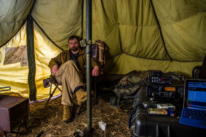
Inside the station
We ended up with just under 70 contacts throughout the US and Canada, since I was able to talk to both coasts often it appears my reach was pretty good. I have ordered a multi band vertical antenna from DX Commander and am looking forward to it as this will allow me to set up away from tall trees.
One of my main goals for this event, besides making contacts, was getting a better understanding of battery management. I am using 2 70Ah gel lead acid batteries. I shut down the station from time to time to compare the reading of Amp hours used on the Powerwerx power meter I have vs voltage readings of idle batteries and found that I can use about 30Ah safely (with an ample buffer) and this gives me roughly 8 hours of continuous transmit activity from full charge.
The goal for my next event will be focusing on voice contacts. Most of my contacts are digital, but I found that the pool of people to talk too in contests runs out eventually so learning to manage voice will help broaden potential contacts in future contests. I have been avoiding voice since, for me, it is more difficult to manage logging and picking out faint signals.
I really enjoyed Winter Field Day and am looking forward to doing more contests and Parks on the Air.
Appendixes available on request to validated .mil users
HF Radio Deployment For Voice and Data
130 FAB, Annual Training (AT) 2019
CW2 J. M., Net Tech 25 June, 2019
Introduction
Equipment
Antenna Placement
Radio Integration
AFATDS Integration
Conclusion
Appendices
References
Introduction
The 130 FAB was tasked with controlling fires for all subordinate firing BN’s (4 in total) during AT 2019. Both BDE and subordinated BN’s were located in Fort Riley, KS. High Frequency (HF) radio, Joint Capabilities Release (JCR), and FM SINGCARS were available for data communications; while HF radio and FM SINGCARS were available for voice communications. Mission Command Information Systems (MCIS) and SATCOM were unavailable during this training exercise. The operational PACE plan prioritized HF communications for both voice and digital. This document describes how the 130FAB established reliable HF communications for both voice and data during the training exercise.
High-Level Architecture
Equipment (R = Required, O = Optional, # = Quantity)
BDE:
(R)(6) AN/PRC 150 HF Radios
(R)(6) RF-1944 Antenna Kits
(R)(6) OE-254 Antenna Kits
(O)(6) Metal Keyrings or D-rings (for mounting balun via pulley)
(R)(1) Laptop pre-loaded with Harris Radio Programming Application (RPA) and NRDI software
(R)(1) Layer 3 Switch (capable of creating multiple secondary IP addresses per interface)
(R)(1) Secure Key Loader (SKL) loaded with appropriate COMSEC
(R)(*) AFATDS
(R)(*) Ethernet networking cable (e.g., CAT 5e)
*Needs (quantity, type, length, etc.) will vary based on TOC layout, number of systems (e.g., AFATDS), and other unit specific requirements.
** The PPP cable should be included in the man-pack configuration for the PRC-150. The part number for the cable is 10535-0775-A006.
BN:
(R)(2) AN/PRC-150 HF Radios
(O)(2) RF-1944 Antenna Kits*
(O)(2) OE-254 Antenna Kit**
(O)(2) Metal Keyrings or D-rings (for mounting balun via pulley)
(O)(2) Zip ties (for mounting balun via pulley)
(R)(1) HF Radio Serial Data Cable (PPP Cable)
(R)(1) AFATDS
(R)(1) SKL loaded with appropriate COMSEC
(R)(1) Laptop pre-loaded with Harris Radio Programming Application (RPA) and NRDI software
*Other HF antenna types (man-pack whip, AS-4701/VRC, etc.) may be used instead. Antenna design and utilization should be based on unique variables associated with the mission (e.g., terrain, distance, TOC layout, available equipment, etc.).
*The RF-19440-AT 150 Antenna Kit requires a vertical platform to elevate the balun and elements of the dipole. The antenna can be elevated using nearly any vertical platform (e.g., OE-254, a tree, or even an M577 queen mast).
Antenna Placement
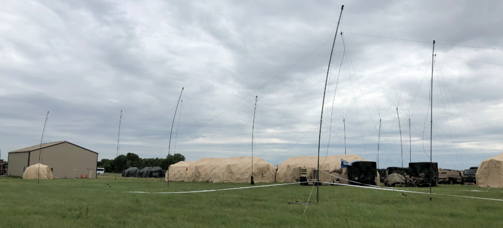
The BDE utilized 6 different HF radios (2 voice, 4 digital) paired with 6 RF-1944 antennas during AT 2019. The radios were required to communicate with subordinate BN’s deployed within the Ft. Riley area of operations (AO). The BDE S6 section conducted a terrain/mission analysis, and determined an average of the various azimuths in the direction of the subordinate units; which was used to plan the deployment of an antenna field which centered the broad (strong) side of the propagation signal to the BN’s. The chosen antenna architecture would potentially support a vast geographic separation between the BDE and each BN (to simulate a potential real-world scenario); while simultaneously supporting all units located within the confined AO.
The S6 coordinated placement of the antenna field with BDE operations; who allocated an entire (long) side of the operations center (TOC). The antenna field placement required a significant physical footprint (approx. 330’ x 50’); and was required to be as close to the TOC as possible (limited by available cabling).
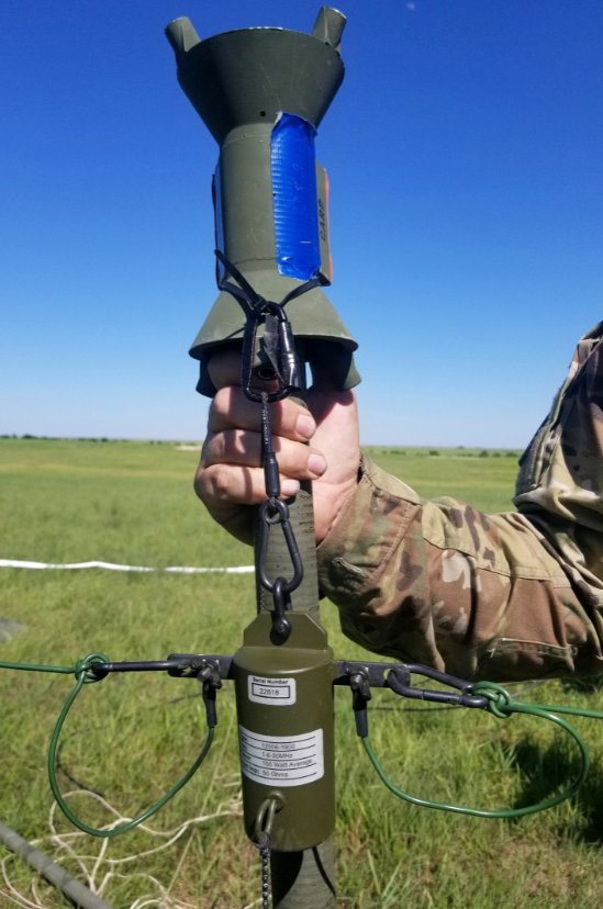
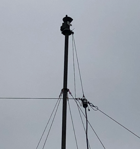
Six antennas were deployed in an Inverted Vee configuration; and were deployed in accordance with the HARRIS RF-1944 installation/deployment manual. Each antenna was mounted to an OE-254 mast, extended to a height of approximately 33’. The balun’s were mounted to the OE-254 feed cone using a zip tie and d-ring (see Figure 1A). The zip tie and d-ring created a pulley system, which allowed operators to lower and raise the balun once the OE-254 was emplaced (see Figure 1B).
Figure 1AFigure 1B
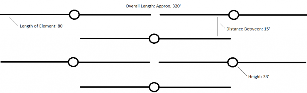
Each element of the antenna was fully extended, resulting in a 160’ Inverted Vee antenna. The diagram outlined in Figure 1C shows the bird’s eye view of how the antenna field was installed. The first antenna in the formation (on the bottom of Figure 1C) was approximately 20’ from the center of the S3 portion of the TOC. All antennas were equipped with LMR-400 coaxial cables (2×200’, 3×150’, 1×87’); and all cables ran into the S3 portion of the TOC.
Figure 1C
The antenna placement at each BN varied. Some BN’s deployed Inverted Vee’s using RF-1944 and an OE-254 (similar to BDE). Some BN’s deployed Inverted Vee’s mounted to masts on the M577 FDC tracks. Others utilized man-pack whips, AS-4701/VRC’s, or whatever was available (or whichever provided the most efficient and reliable connection to BDE).
BDE Antenna Farm
Radio Integration
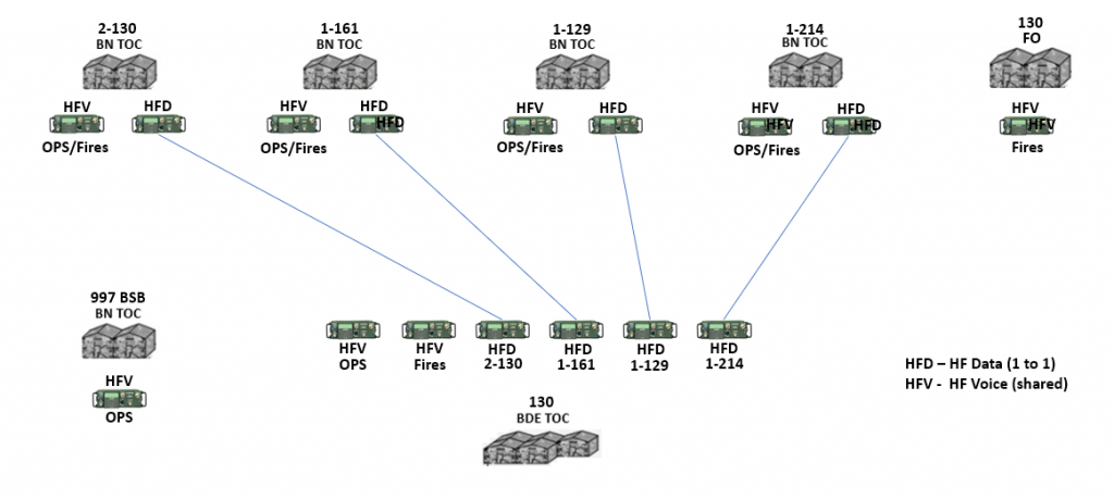
Fifteen (15) HF PRC-150 radios were used to link communications between BDE and BN’s during the training exercise. The distribution of those radios consisted of the following:
BDE –
[4] Data Radios
[3] Voice Radios
BN –
[1] Voice Radio
[1] Data Radio
All voice radios across the BDE were loaded with the same configuration, using the Harris Radio Programming Application (RPA) software. The voice configuration leveraged the Automatic Link Establishment (ALE) radio mode; which consisted of a single channel group, 5 channels, 5 frequencies1 (ranging from 2 – 14 MHz), and 8 different stations. Appendix A2 provides the step-by-step instructions that were taken to program each voice radio.
The data radios across the BDE were loaded with slightly different configurations; which were also built using the Harris RPA. The data configuration leveraged the Harris 3G – IP Networking radio mode. Four channel groups were created, each representing a one-to-one link between each firing BN and the BDE.
The BDE was only allocated 10 HF frequencies to distribute between the 4 channel groups. This would generally be considered inadequate3; however, all units within the AO were well within range of ground wave propagation, which negated the need for a distributed range of frequencies needed to communicate reliably. A larger geographic separation would require a much larger pool of frequencies per channel group – to account for atmospheric changes (e.g., weather, time of day, etc.).
All radios resided on the same wireless radio subnet, which allowed any BDE programmed radio to communicate with any other BDE programmed radio as long as they were set to communicate on the same channel group. Channel groups were generally assigned to BDE/BN pairs, to simulate a direct dedicated link. Each radio also resided on a unique subnet for their respective local area network (LAN); and generally acted as a gateway (or Exit Router) for any local systems utilizing the radios as a data transport (e.g., AFATDS).
The BN architecture consisted of the radio being directly connected to an AFATDS system (a.k.a. PPP Serial Direct Method). This connection required a PPP serial cable to interconnect the AFATDS and the radio. Step-by-step instructions for establishing a connection between AFATDS and an AN/PRC-150 can be found in Appendix B.
IP address settings for the radio wireless network, the IP network used to communicate with computers (e.g., AFATDS), and all IP routing information were contained within the configuration. The 130 FAB S6 leveraged a generic FAB data and voice RPA to integrate HF data communications in the environment. The generic RPA configurations can be found in Appendix C4.
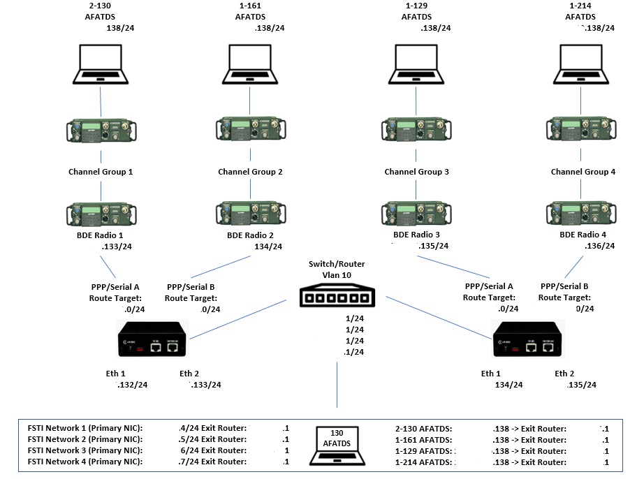
The BDE architecture was slightly more complex. It consisted of multiple AFATDS interconnecting with the 4 BN radios via an Ethernet IP network. The S6 team leveraged the existing Ethernet network interface cards on the AFATDS systems to tie into an Ethernet LAN, which was distributed using a layer 3 Cisco Switch. The switch was then connected to a pair of IP 6600 routers. The routers then communicated with the radios via a PPP serial link. This architecture allowed AFATDS systems to route packets through an existing Ethernet LAN, through any of the interconnected radios, and eventually to the desired BN AFATDS. The design was flexible enough to allow a single or multiple AFATDS to communicate with all BDE AFATDS. See Figure 2A for the LAN/WAN architecture.
1The HF frequency range allocation to the BDE was significantly lower than what was requested.
2 Appendix A references a pre-built RPA configuration. The RPA configuration must be completed and made available prior to attempting to program a radio. See Appendix C for generic RPA examples.
3The reference document “LRC HF Radio Plan and Frequency Management”, prepared by CGI Federal, provides best practice recommendations for allocating frequencies to channel groups.
4The generic RPA was provided to the 130 FAB S6 by Mr. CM, CGI Federal SED Contractor.
AFATDS Integration
The BDE AFATDS system(s) integrated into the architecture outlined in Figure 2A via a single ethernet network interface card (NIC)1. Four separate Fire Support Tactical Internet (FSTI) connections were created and assigned to the Primary NIC (see Figure 2A for FSTI network details). Once the FSTI networks were created, the individual AFATDS destinations (for each BN AFATDS) were created. The appropriate FSTI networks were assigned to each destination AFATDS (e.g., FSTI Network 1 would be assigned to 2-130 AFATDS). This allowed the BDE AFATDS to communicate with all AFATDS simultaneously through a single ethernet interface. When multiple BDE AFATDS were utilized, the same process was taken; with the exception of the FSTI Networks having different local IP addresses (e.g., AFATDS 1 would be x.x.x.4 for FSTI Network 1, while AFATDS 2 would be x.x.x.5 for FSTI Network 1).
A data sheet/radio plan should be created
Conclusion
The BDE HF deployment was generally considered very successful. The HF (data) radios proved to be extremely reliable for the AFATDS communications. Once the routing bug in AFATDS was identified and corrected, there were no identified outages and/or issues reported with the connections.
The HF Voice radio deployment wasn’t quite successful as the data radio deployment; mostly due to the operational change that was required to adapt to the way the radios functioned. Unlike FM broadcasts on certain Net ID’s, the HF voice radios required calls to be made to certain parties; and those calls to be terminated once it was complete. Other than the change in how it worked, operators mentioned on multiple occasions that the call quality on the HF radios was much better than the quality of FM communications. Overall, it was a successful implementation BDE wide.
Finally, the antenna field placement had little to no impact on TOC placement. Power distribution was handled on the opposite side; and environmental control units were easily distributed on either side. Even though MCIS was unavailable during this training exercise, there was plenty of room available to deploy a JNN/STT.
Appendices
All referenced appendices can be found as external attachments to this document.
References
All references can be found as external attachments to this document.
AFATDS IP 6600 Method Example
LRC HF Radio Plan and Frequency Management
AppC Troubleshooting AFATDS networks settings
HF Data CMDRs Overview
LRC 25U HF Radio system function test, maintenance and troubleshooting Guide
In short, POTA is taking amateur radio equipment to a park listed on the POTA database and making contacts from there. The people that participate in this have a wide variety of setups ranging from a small battery and radio set on a picnic table to setups that can be in poor weather and sustain operations with some form of power generation. My goal is to lean to the latter, sustaining radio operations for several days away from power.
My last overnight trip was Perry State Park on Lake Perry, KS. The spot was beautiful and I had a great view.
Lake Perry, KS
Since I don’t have a mast, I have to select a spot with a tall tree to get a dipole antenna in the air. I took some fishing weights and put those in a tennis ball with paracord tied to the weights. The weights are silicone calked inside the ball. I use this to throw a line into a tree, which I use to hoist the dipole feed point up as high as I can. The ends of the antenna I either stake in or find other trees to tie off to to make an inverted V. Once the antenna is in place, I can set up the campsite since my feedline to the antenna will dictate where I can go. Ill have to be cautious of dead trees as these can be dangerous. Setting up or tearing down the entire thing solo takes about 2 hours. Once in operation it looks like:
POTA Station
I weighed the equipment and found:
200lb Gel lead acid batteries (140Ah), solar panel, and cart
100lb M1950 Tent and Yukon stove
100lb Personal care items, rucksack, cot, sleeping pads, camp chair, food
15lb IC7200 and accessories
10lb Tuner and power distribution
10lb Raspberry Pi, Software Defined Radio (SDR), and tablets
10lb Handheld Transceivers set with charging components
10lb Backup laptop
10lb Antennas and feedline
465lb of equipment. Some of the personal care items are not required such as the chair and cot. The tent, batteries, and radio can all be brought down in weight with items made to be light and I can get those over time. The current setup works well and my Lake Perry POTA activity was alot of fun.
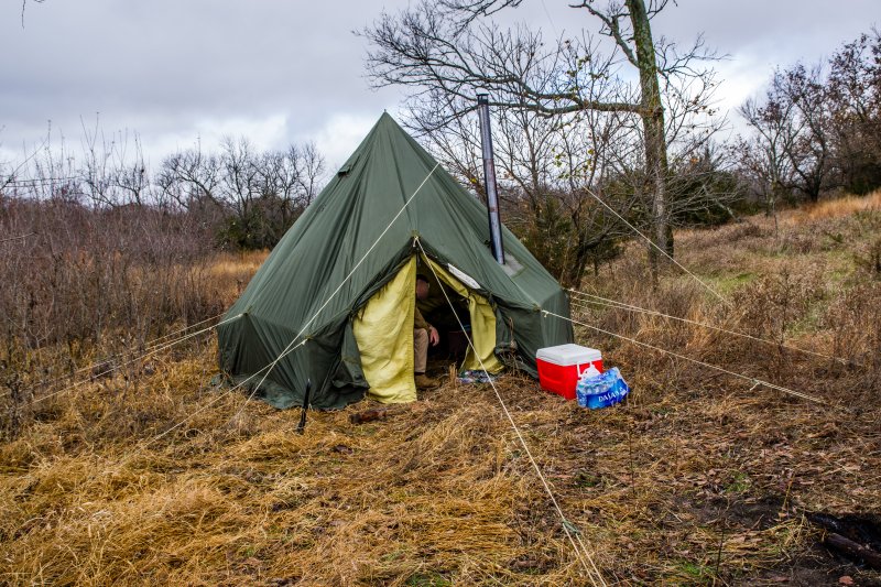
The Yukon stove really works well. There isn’t much info on it to be found using with wood as a fuel like I am, and my experience with it isn’t helpful since we used vehicle fuels (diesel/gasoline) to burn in these when I was using one on active duty. I have the fuel burning plate, but do not intend to use that. I have no idea how we didn’t start several fires with these when using gasoline in the 80s, luck I guess. The door on the stove does not seal well, so regulating temperature when burning wood is largely dependent on bringing the coals forward or rearward and feeding the fire with smaller pieces more frequently as opposed to stuffing it. I found it wont burn overnight with wood so ill have to set an alarm after a few hours to feed it so it does not go out. The TM mentions coal or wood as a fuel, but does not go into detail. The stove works great to cook on and during my trips I have a constant supply of coffee or tea. In summer ill have to make a cooking fire outside since this stove produces quite a bit of heat.
I am really enjoying POTA activities and am looking forward to doing these as often as I can.
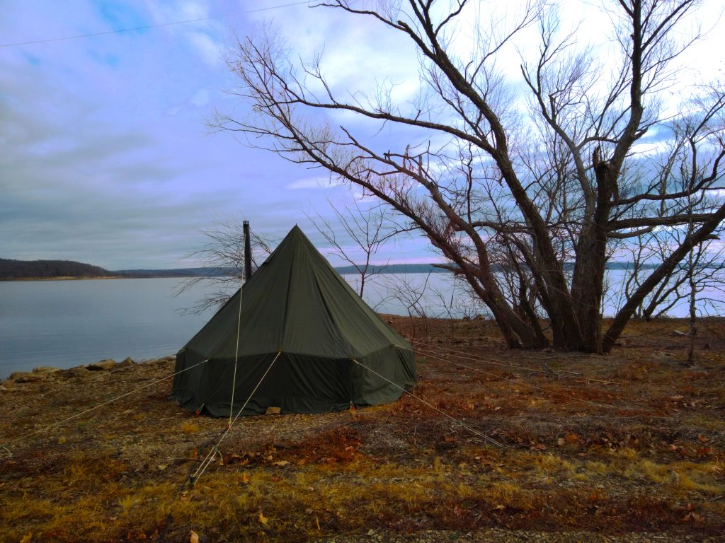
The cart concept would work with some very expensive items, namely lithium iron phosphate batteries, and winter tents that are light but can contain a wood stove. The cart with shelter and radio equipment was simply to heavy to move more than a few hundred feet unless on perfect terrain, and then it was slow going. I won’t abandon the concept, but ill have to wait to get the items required to be portable. In the meantime, still with an eye to winter field day, I did get a surplus shelter that I have quite a bit of experience with while stationed in Germany in the 80s. It is an M1950 hex tent, and I have coupled it with a surplus Yukon stove that I have had, but not had a use for, for years.
The shelter has ample room for the radio equipment, stove, and a second person. Its 80lb, added to 2-300lb of radio and camp gear, so this will be something that will require transportation of some kind (ATV/Horses).
I tested the setup at my farm, then took it to Lake Nebo, KS for a “Parks on the Air” activity https://parksontheair.com/. Parks on the Air encourages radio operators to take their equipment to a national or state park to make radio contacts from a field location. This was my first attempt at doing such an event and it was successful, in that I made the required number of contacts. The terrain at Nebo is not ideal for the antenna I have, and my ability to be heard on the airwaves suffered. It was fun, and I definitely plan on doing more parks on the air activity since it combines my love of camping with radio. I still need to evaluate what equipment I must have to get lighter and more organized, but with the way that most parks/campgrounds are set up moving the equipment from a vehicle to the campsite is possible without much difficulty.
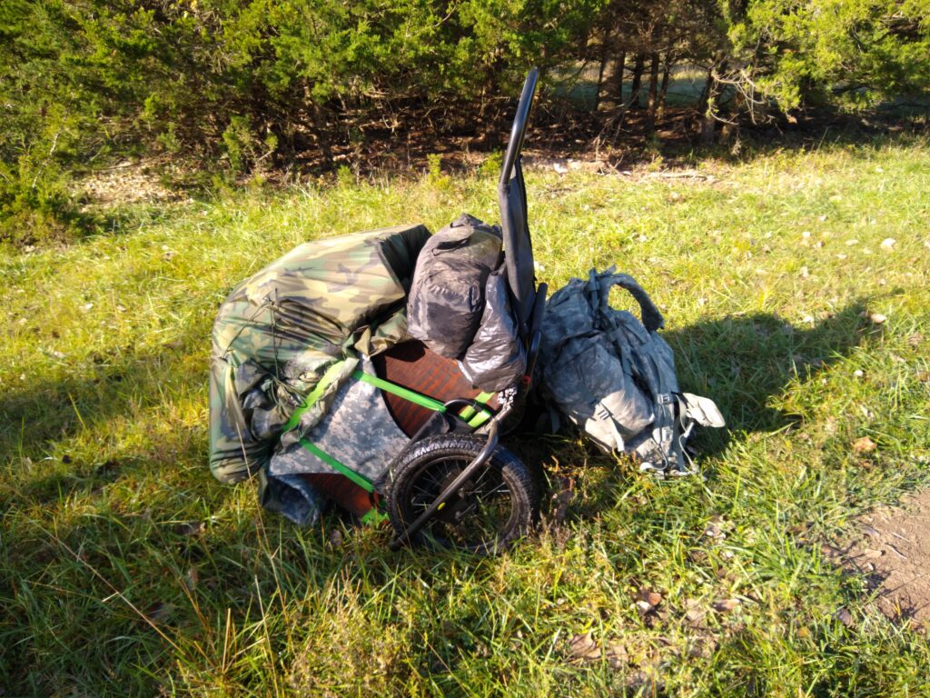
Inspired by OH8STN (http://oh8stn.org/), and in anticipation of Winter Field Day (https://www.winterfieldday.com/) I decided to make a portable station. For the most part, it is my normal home setup on a cart. It is heavy but it works, refinements will be reducing weight. When put together for travel it looks like:
Portable station packed for travel
The items aren’t ideal, but this was made from scrap and items I had on hand. The only items I purchased for portable use was the cart, a Rambo Bikes cart made for a fatbike but can double as a hand cart, and a GPS dongle for time which is required for some digital modes. Additionally, a 100w solar panel from Rockpals provides recharging capability, which I got on sale.
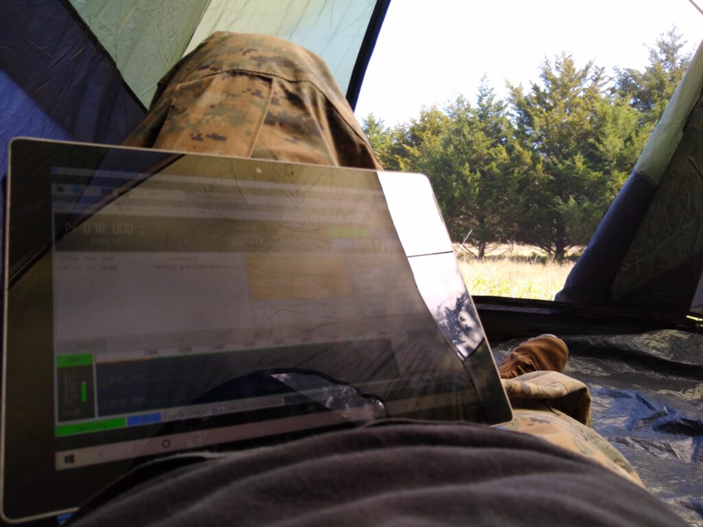
During Setup
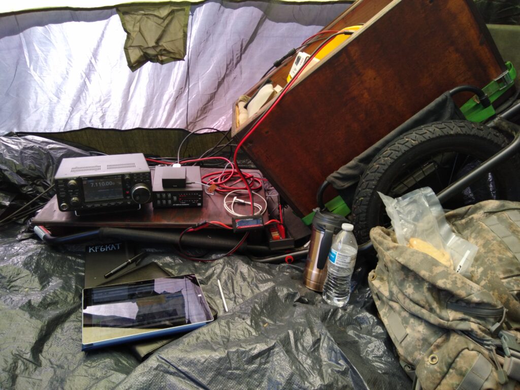
Station in use
The batteries are the same as my home station, I got a fresh set and used the older ones for portable. They add the most weight at 100lb of Gel lead acid battery, but I get 140Ah from it. The box is weatherproofed, but ill need to refine how I cover and load the cart for rain. The box lid doubles as a tabletop when it is inside the shelter. I added an IC7200 to the setup since its made to take out in the field and less delicate than the IC7300. A couple of old tablets provide VNC (remote desktop) access to the Raspberry Pi, which handles digital modes. Antenna is a multiband Windom dipole that uses trees for height in an inverted v configuration.
Moving the station is workable, but weight reduction will help make this easier. difficult terrain will be a challenge in its current state.
It works in testing, I get the same reach as my home setup, so I am happy with it. The next step will be to find some local campgrounds, hike in, and set up there to see how far I can pack this and what can be done to improve its portability.
A friend of mine suggested we participate in Field Day 2020. Having not done any contesting before, much less in the field, I wasn’t sure how this would work out but I really enjoyed it.
Our setup was a simple 12v car battery and our HF rigs. I had handheld 2m radios but we didn’t use them very much. Our antenna was an inverted V dipole that we shot into the trees with a bow, a fishing pole, and guy line. We set up a campsite and then focused on operating the station. My friend made a significant number of voice contacts and we discovered the rules gave an advantage to digital contacts. I have used digital modes mostly in JS8Call and Contestia, but I could only make a small handful of PSK contacts. The action seemed to be in what sounded like JS8Call, but I found later the mode was FT8. Having spent some time since learning this mode, I should be in good shape for the next field event.
We ended up needing a generator a couple times, which introduced interference with radio operation. For the next event I’ll be looking for some foldable solar panel sets to charge the station batteries and a Raspberry Pi/tablet combo for power efficiency with the digital aspect. My home station battery setup can run for a few days without sun, but that is mostly listening so i’ll have to work up the math on contesting, which is a great deal more transmitting, thus power consumption, than I am accustomed to.