

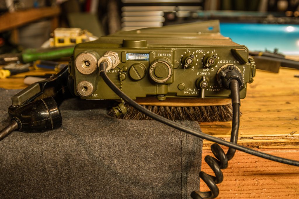
I was looking for an old, unrepairable radio to hide an Icom 880H Amateur radio in and found a perfect example. This radio would be period appropriate, being produced in the 50s and its even the Artillery type, good match for my 2-130th Field Artillery marked truck. I wanted unrepairable since I didn’t want to mess up a potentially good radio and ruin some history. I got this from http://fairradio.com/ Fair Radio Sales who took the time to dig up a salvage radio for me. I hope to get one of their repairable AN/PRC-9 radios soon as well, maybe an AN/GRR-5 too.
The M37 truck has an antenna, antenna mount, and working speaker on it, but no radio base, so I’ll have to come up with a way to mount the radio, but it will be neat to have a working radio as I am driving the truck.
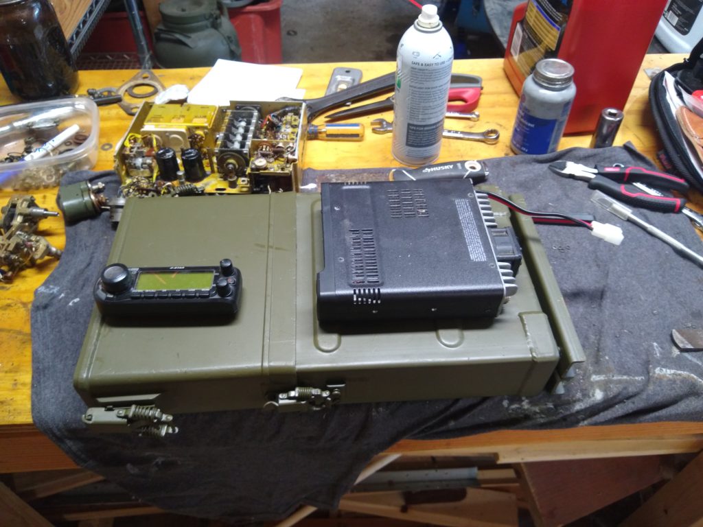
The AN/PRC-8, 9, and 10 series of radios came in versions for Armor (AN/PRC-8), Artillery (AN/PRC-9), and Infantry (AN/PRC-10). AN/PRC stands for Army/Navy Portable Radio Communications. A good article describing the series can be found at http://www.n6cc.com/prc-10-infantry-radio/. As a signal officer, I am glad they abandoned the Armor/Artillery/Infantry versions, but it likely was a good way to make this set (more) portable given the technology of the time. It is quite a compact radio, surprisingly, the Icom 880H just fits in the battery case.
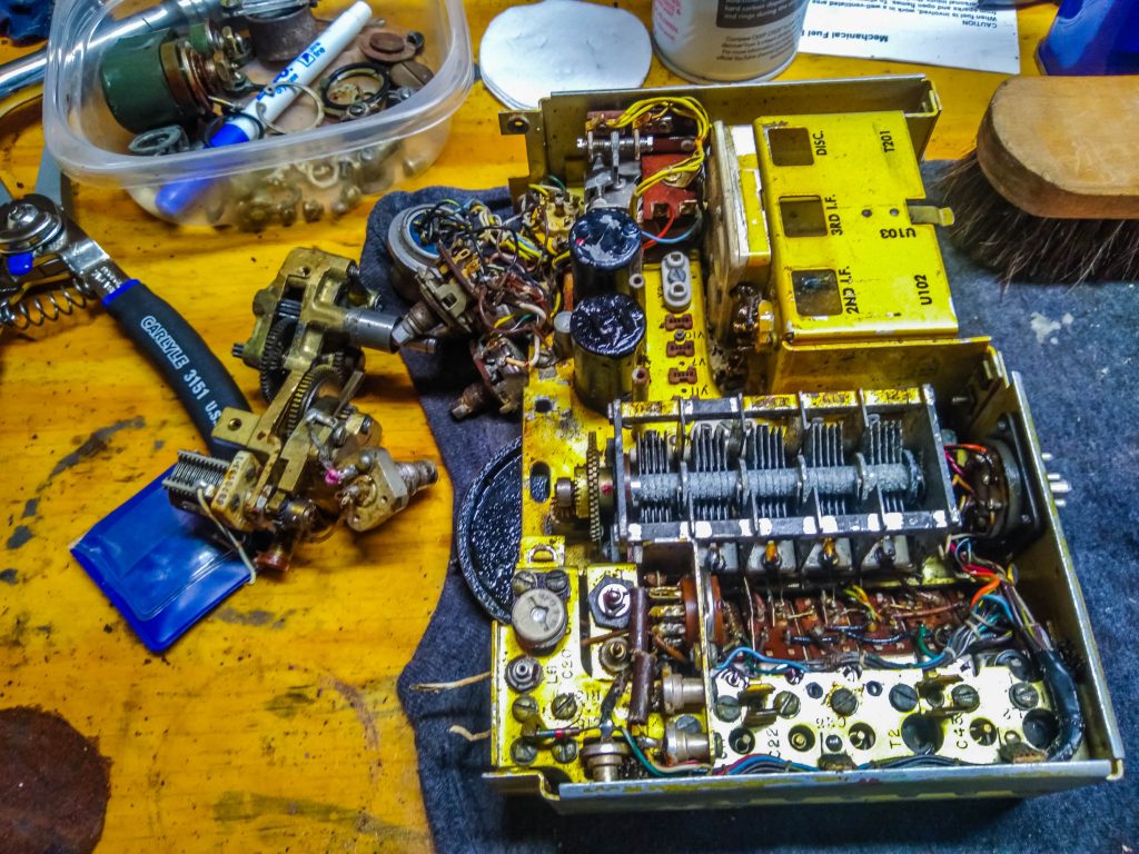
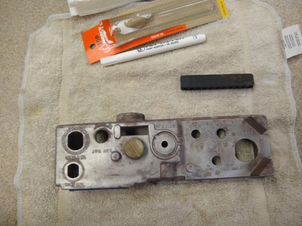
I asked for a salvage radio, and this example was quite corroded inside, thus not really salvageable; but this is what I wanted as it will just be a place to hide the Icom 880H. I will preserve the tune dial gearing which is still running smoothly, rewire the handmike to work with the Icom, and maybe try to repurpose the dials to change channels or volume control. The Icom 880H has a remote control head which can mount in the glovebox to be handy, but not visible.
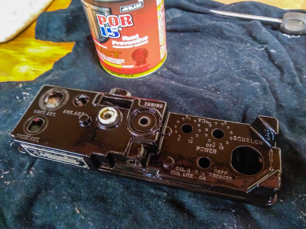
I have heard good things about POR-15 and I’ll try it on this radio. Topcoat will be OD Green. As I get the wiring and mounting worked out, I will post these details.
Restoration and Adaptation of AN/PRC-9 (August 2022)
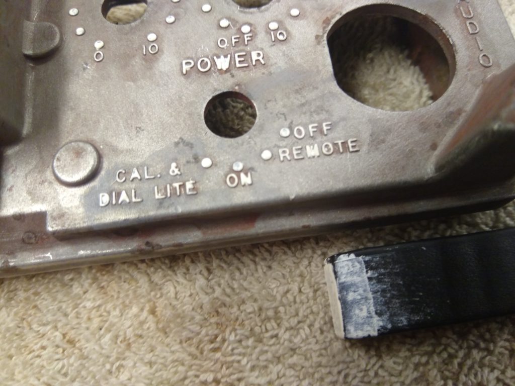
POR-15 will be great, it is tough stuff, but I put it on too thick. One thin layer of it then OD green would have been sufficient. I did two, I’ll strip it and start over. The paint pen also isn’t going to work, partially because it flows to fast and is not crisp, but the thick layer of paint isn’t helping either. I am not sure how I will tackle the fine, crisp lines needed for the raised metal. Stencils for the original markings should be doable (ORG, CH, POINTER ADJUST labels), but the raised metal is going to be a challenge.
The battery box will work great for the ID-880H, but sadly I’ll have to cut a hole somewhere for power, I/O, and ventilation. There is a handy stand built right into the battery box, two legs that swing out, that could be a good candidate for hiding a hole underneath. The battery box was beat up, but I was able to (slowly) coax it back into shape with a softwood lever.
Painting, take two
POR-15 is difficult to strip, which means it’s tough and durable so that is ultimately good news. Modern stripper won’t remove it, but it does soften it enough to gently pick it off with and Exacto knife. Tedious be effective, just be cautious about gouging the surface of the metal.
Painting rehearsal
The local hobby store in Topeka (Dee and Me Hobbies) suggested paint on a piece of glass or something and press the paint on. It seems to work well, but glass seems too stiff causing paint not to apply, and standard rubber is too soft which causes paint to flow past the letter faces. I found a drill bit holder that looks to have promise, made of stiff rubber. I’m applying an even, thin coat of paint then pressing it on the letter faces. I’ll get some practice then try again.
Second Coat of Paint and Padding for 880H (September 2022)

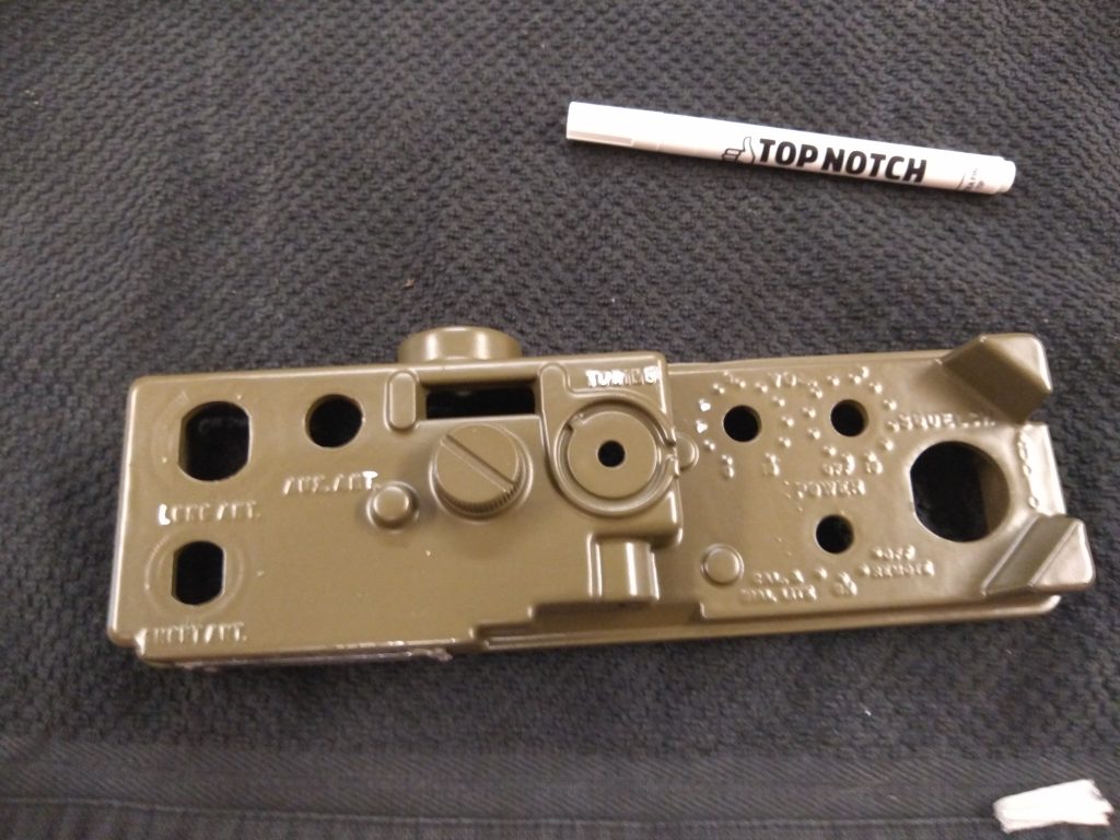
Turned out much better with a very thin coat of paint. The letters are crisp and should be easier to paint. I cut an 1 1/2 in hole in the battery box where the 880H vent is to get warm air out of the setup. I used a Dremel to make the rough cut and a round file to finish. I’ll get a rubber gromet for the vent and the power connection. The foam is some stuff I had lying around, and it will work great. Not too hard to cut and will cushion the radio while getting bumped around as I am driving.
I found a very helpful person that has Icom microphone elements, which I will use rather than adapting the old carbon mic in the H-33 military mic. It should be straightforward to hook up since it will be an Icom element.
I hooked up the radio in the battery box and listened to the local NOAA weather station, it was slightly muffled, but not as bad as I thought. The truck has military speaker as well that I will hook this radio too, I should be able to hear even while driving with little issue.
Adapting Icom HM-133 handmike to H-33
I didn’t really think about it when I first thought this up but wiring this won’t be as simple as reconnecting wires around. The microphone and handset speaker isn’t the same between the HM-133 (Icom) and H-33 (mil). The circuitboard in the HM-133 provides some supporting electronics along with some voltage. The actual (tiny) microphone in the HM-133 isn’t labeled either, it surprised me to find how miniature the mic is compared with the H-33 carbon mic.

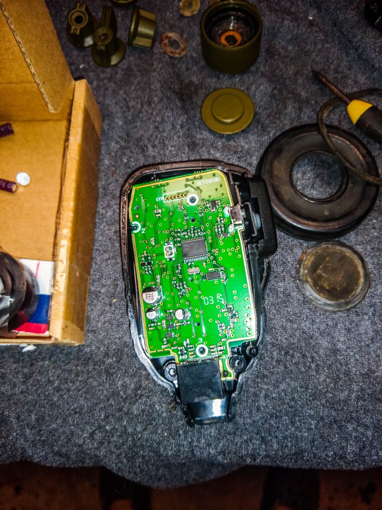
I have some choices to make in wiring this. I can convert the audio from the mic/handset speaker/radio to the original elements in the H-33 somehow, use modern mic/speakers in the H-33 and assemble an approximation of the supporting electronics, or just take the circuit board from the HM-133 and put that whole thing in the radio and feed the (modern) mic element from it. Finding information on the components is difficult, but I finally found a resource I can use to understand more clearly what I am doing. https://www.tinymicros.com/wiki/Icom_HM-133 has extensive notes and links to datasheets on the components, including the specific mic, a Hosiden KUB2823 Microphone, at least that looks correct. Now instead of guessing what needs what if I make some supporting electronics, I can do this accurately.
I did get a collection of scrap components from https://www.7000mic.com/, which gives me some great options, but I really need to dig into the datasheets of these components, understand what they need and can do, so I am not needlessly wasting these items.
The earpiece hopefully will be straightforward, there is a speaker jack in the back of the radio I can use to feed the military loudspeaker in the truck and the earphone in the H-33, although I will have to get specific about what is being output at this jack and what the two speakers expect. Interestingly, one of modern earpiece speaker elements I have fits perfectly in the spot the old mil element did.
If I do end up just using the whole circuitboard from the HM-133, there is plenty of room in the AN/PRC-9 body to fit, since the components have been cleared out it minus the freq dial and gearing which I will preserve to keep the appearance of an AN/PRC-9.
As a Signal officer, I know electricity and radio theory basics, but I never really had to dig too far down into determining what a schematic is telling me. My enlisted days after being a 13B cannoner, in my 25 series signaller time, I did tuning of 12 series radios but that was a long time ago and I didn’t really have to interpret schematics as much as just know what to look for and what components might need replaced. I soldered and turned pots alot, but never really dug into ~why~ the circuits were as they were. Modern radios lend themselves even less to this as they generally get repaired by board replacement, which I found right before I went to OCS in my last days in the electronics shop with the SINCGARS. I really need to dig down and understand clearly what I can and should do in hooking this up to get a good result.
Once I get the right combo and get it working I will detail how I got there, the notes and links at https://www.tinymicros.com/wiki/Icom_HM-98/HM-133_Internals should get me on the right path. I have quite alot of study ahead of me, even though I wasn’t expecting it, I am happy to learn about something I have been wanting to understand for many years, electronics.
Getting Started with Connections

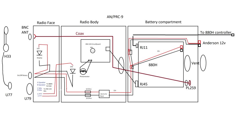
I found some old speakers that were trash and got the speaker cable from that. On the U77/U79 connector, pins A and B are the speaker, so I soldered those in, plugged in the cable, and got audio through. I have to test the PTT function on the radio and how to get the mic part through. PTT on this radio appears to be more than just a press switch, the HM-133 sends a bitstream to PTT then a bitstream to key off. There is a PTT on the schematic that may just be simple key on/off and I’ll have to test that, but I am not optimistic. If it does not, I’ll have to see the behavior of the HM-133 PTT and see how I can extend that.

Mapping the U77/U79 connector to the 880H RJ45 jack should be straightforward from a physical wire perspective, but what properly goes where will be another story. Up next will be testing behavior of PTT and mic to see what my options for extending those are.
H-33 Military Handmike

This mic has been confusing me for a bit, I really didn’t want to totally disassemble it, but continuity checks were not agreeing with documents I have found.
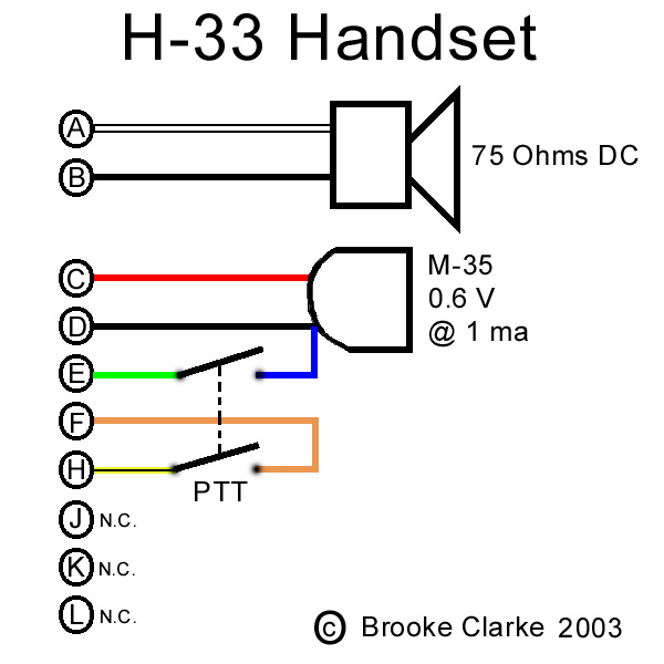
If I am to use the HM-133 circuitboard, I will need two wires for speaker, two wires for mic, and two wires for PTT. In testing the PTT from the HM-133, its a simple push switch so I can just loop in the H-33 PTT (F and H, brown and yellow), but the brown cable didn’t pass continuity. I exposed the wires on the H-33 and connected at the end of the brown on each side and found that if I flex the coiled wire, I get connection sometimes – meaning the cable itself is shot internally. Since I purchased this as a non-working display piece, this is fine/expected but I’ll have to get a replacement coiled wire or simply use another H-33. At least I got to see the U77 connector disassembled, which is surprisingly easier than I anticipated.
My current plan is to use A/B for speaker, C/D for mic, and F/H for PTT. My simple RadioShack soldering iron that I have had for decades really isn’t sufficient for this (tip to large and burned up), so I got a better Weller iron. I really wanted a Weller 1010 but went with the consumer 30w version for a third as much and it will do what I need done. I also found an assortment pack of diodes, resistors, capacitors, LEDs, and breadboard since I really need to get better with electronics. I need to be more like Sayid from Lost – he could build radios from junk like all signal officers should be able to.

October Progress

Painting the raised letters and getting an acceptable result was a challenge, but I was able to accomplish this using the stiff rubber drill bit holder (any flat piece of stiff rubber with just a little give would work) and painting this while holding it upside down. I used an Exacto to gently scrape paint the flowed/wicked despite being upside down. I would guess there is a better technique out there, but I couldn’t find it and I ended up with a decent result. The tuning knob works to move the frequency dial even if this isn’t connected to anything. Ill place an LED where the incandescent bulb was to illuminate the dial like the original.

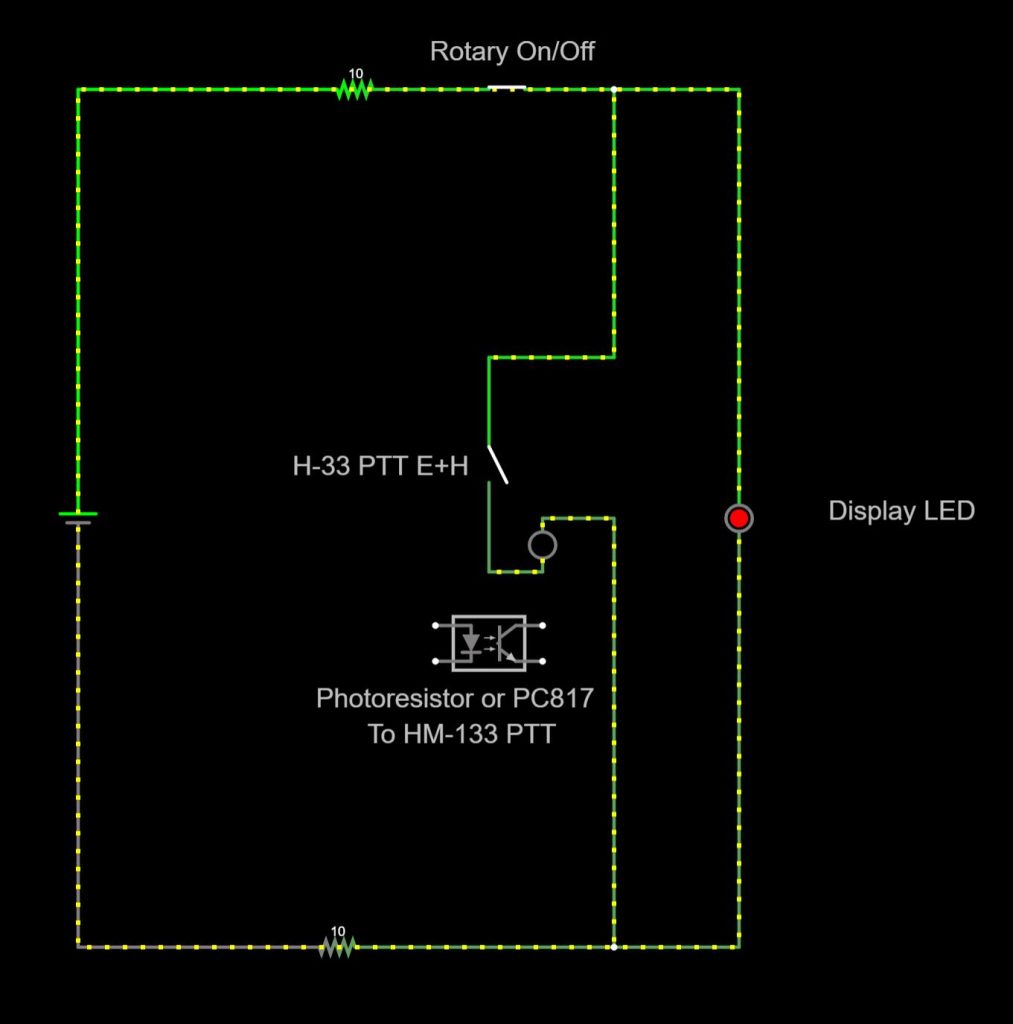
The PTT problem was difficult to overcome, but I think I have it nailed. The U79 had oil in it to free the pins and this appeared to be just conductive enough to trigger the very sensitive HM-133 PTT circuit. Disassembly of the U79 as easier than I thought, and after cleaning it, the U79 no longer triggers the HM-133 PTT. The H-33 PTT still does trigger the HM-133, even after detailed cleaning. I was able to overcome this with a photo coupler – test rig below:

I bought an assortment of electronic components and it had a photo sensitive resistor and LEDs, so I hooked the H-33 PTT to light and LED and the HM-133 on the photo resistor. This worked reliably and I was able to make a test call on 2m using the H-33 fully set up. I will order a PC817 Optocoupler for the final assembly. With the last technical issues out of the way, I can work on final assembly and get it in service.
Finishing up
The radio is complete. The photo coupler solves the touchy HM-133 PTT problem reliably. I did put some electrical tape over the contacts in the mil H-33 PTT as it seemed to cause the LEDs to flicker sometimes without it, likely since they are slightly compressed when assembled and the connector leads are very close together. 10 Ohm resistors used to bring the buck delivered voltage down a bit from the top edge of the LED specifications. Talked to someone on 2m that stated my audio was good, so this setup seems complete electrically.

Now that it is complete, I will post the details in a separate post since this post was long and has some wrong turns in it. I also have to stencil on the ORG/CH table that was on the original to be completely done, but this will go nicely with the M37 when it is finished. Most photos of the M37 with a radio shows it mounted in the bed area, but I would like this radio in the cab. Hopefully I can find a photo of such a setup.