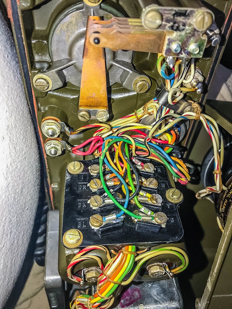
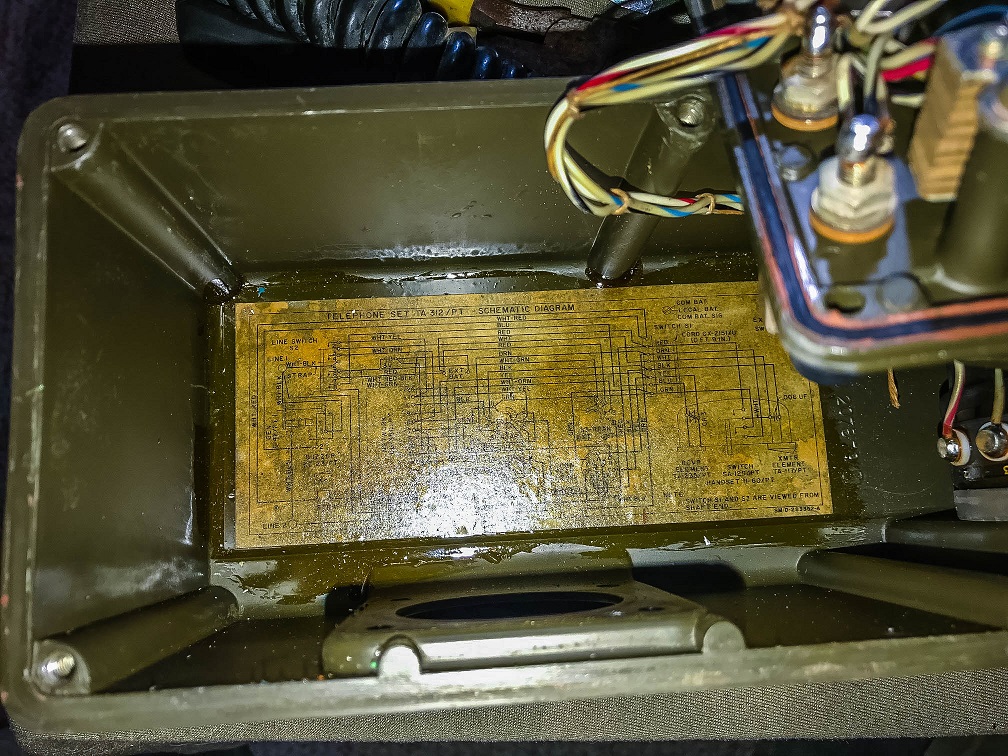
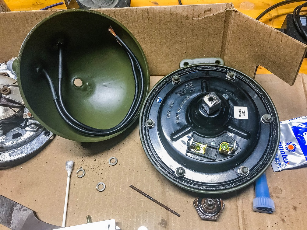
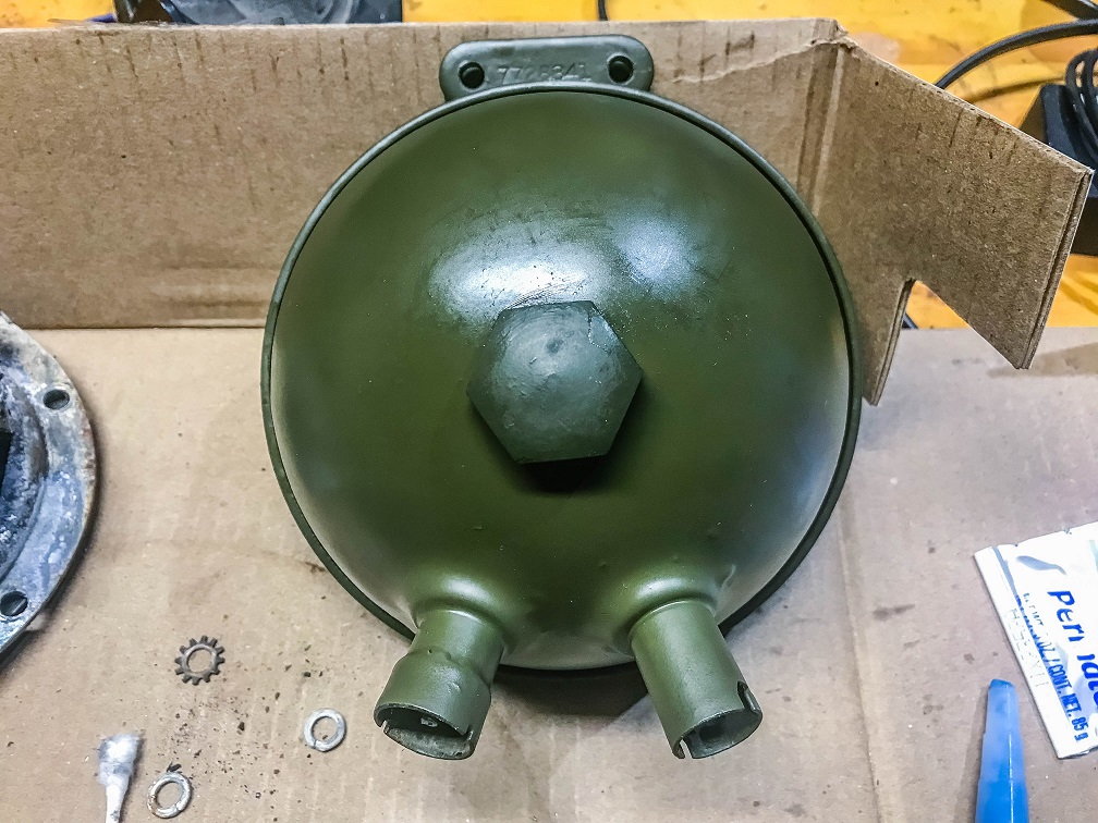
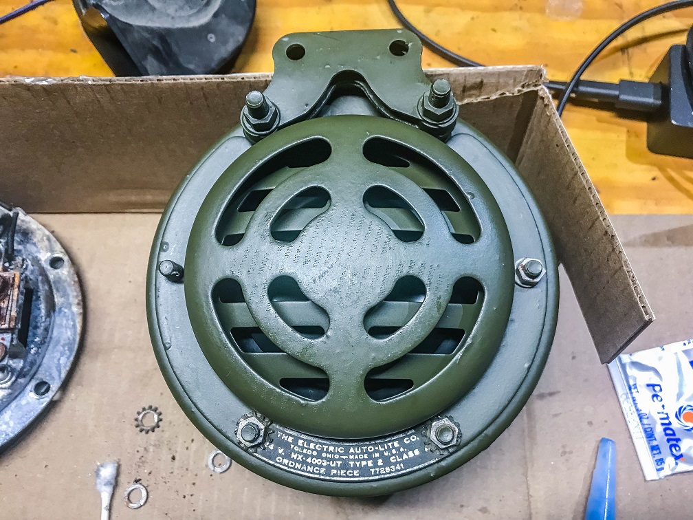
The original horn in the M37 matched its original electrical system, 24v. If you have a converted M37 there really isn’t a 12v horn that directly replaces a failed horn. On my truck, there is a modern 12v horn concealed that works out, but I wanted to use the original part if possible. The original horn was corroded in the interior, so this ruled out using a 12/24v converter. Vintage Power Wagons sells the 12v HYF-370 horn, which does fit in the MX-4003-UT housing with a bit of fitting.
The screws holes holding the HYF-370 together need drilled out a little to fit, and the HYF-370 came with a gasket between the two halves so I used a small amount of permatex with the gasket to compensate for the slightly larger holes. The original horn housing is held together with a large hand turnable part (below) which the HYF-370 does not have a hole for, but it does have a bolt shaft in the center so a metal dowel works to hold the thing together. Shaping and tapping this was fairly straightforward, I used M8x1.25 and 10NF32 taps, but I am not sure how consistent this would be.
I put terminals on the wires, soldered the other end to the douglas connector, hooked it up and it works. Sounds appropriately truck like, even if it likely does not sound exactly like an original.
If you have an M37 with 12v, and your horn isn’t working, this is one way to get this working and still look mostly correct.
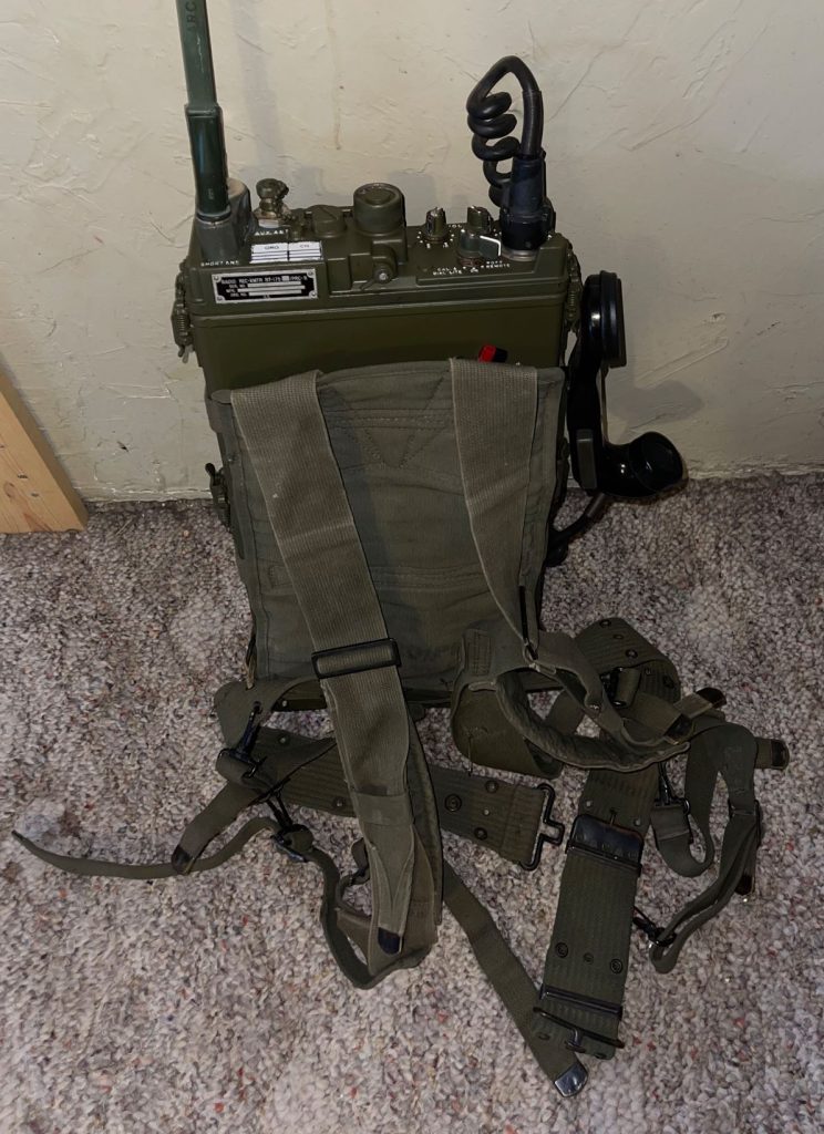
Found a manpack harness at Apex Gun Parts Gun Parts & Accessories (apexgunparts.com) who seem to have a wide selection of various parts. The WWII era belt was from Overlooked Surplus in Leavenworth, KS Overlooked Military Surplus (wwiigimilitarysurplus.com). Overlooked Surplus has a very interesting selection, and I will definitely be stopping by there more as the budget allows. They have an old field desk of particular interest to me.
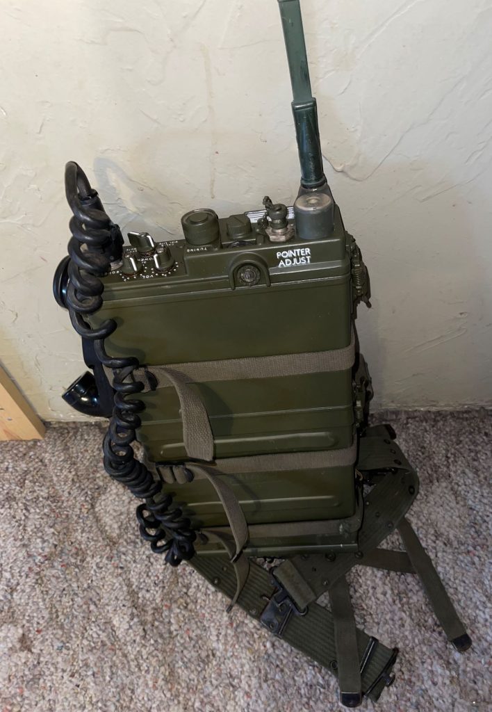
The painting was done with stencils I made on a Cricut machine, which did ok but difficult to work with the tiny lettering needed. I got it, but it took a couple attempts. The ORG | CH table above the dataplate I assume was for operators to jot down frequencies of units they worked with. Small space to write, however, no idea how practical this was in the field. The other marking was “Pointer Adjust” and the nearby dial does move the frequency dial needle. I assume they found a known stable frequency and adjusted the needle to match that. These radios were continuously tuned, as opposed to later PRC-25/77s or modern SINCGARS where turning the tuning dial stepped a set amount of kilohertz.
Pretty happy with the final result and it is now ready to go in the truck when it gets back from service. I still have to work out the antenna and mount, since the installed antenna wont work well with 2m radio and the flex antenna stuck on the radio isn’t hooked to anything – it also is tuned for MIL frequency range. The flex antenna does look nice though. For the vehicle antenna, which will connect to the BNC Aux antenna connector, I am looking at a Firestick 2m type which should look similar or at least not too out of place. It comes in black and the conductor is spiraled over the fiberglass whip, but hopefully is fine after paint.
Normally this is pick two, but for old military vehicles, it seems to be pick one (and probably best to pick ‘good’). I have been fortunate to find people that are familiar with this era of machine and find this project interesting. I don’t think the truck will be ready for Winter Field Day 2023, but it is getting closer.
I bought the engine hand crank as an accessory, while attempting to start the engine with that is very risky, it is good for turning the engine for timing and such. I am glad I got it for this purpose. The radiator has an access port for this so even with the engine completely assembled for operation, this crank can be used. The crank itself wasn’t very expensive, I think under $100 or so from Vintage Power Wagons.
Looking forward to getting the truck back and on the road.
The Army Signal basic course is generally designed for a track beginning in signal units. Some new lieutenants may find themselves assigned as an S6 in some other type of unit and there isn’t much opportunity to figure things out before finding themselves having to know things that really weren’t covered in training. Here are the habits I developed to ensure that me, my section, and my unit were prepared to communicate effectively.
Find out what the unit is supposed to have
Find out what the unit actually has
Find out what the maintenance status of this stuff is
Find out how the unit operates by doctrine and how communications are part of this
Find out how the unit actually uses the equipment in operations
Find the TMs, and any locally made documentation for systems
Find out the capabilities of the equipment your unit is assigned
Find out if there is any training time available that you can request for these systems
Find out the training events of the unit and start planning for these 12-24 months out
Finding out what the unit is supposed to have should be fairly straightforward. Your S4 or supply Seargent should have access to print the Modified Table of Equipment (MTOE). The MTOE is the allocation of people and equipment for your unit and will list almost everything. Analyze this and extract communications equipment and to what section it belongs to. I found it useful to make a slide deck of sections and the equipment they have, with photographs of the equipment. Section leads stated they found this reference helpful when doing inventories particularly with little used equipment. This reference will have value for you so that you know exactly where equipment is supposed to go and who is responsible for it.
The unit may have communications equipment that are additional authorized items, or they have issued for some special purpose. Accounting for these and including them in your inventories will give you a complete picture of what the unit has (or should have). Some items are authorized for purchase based on unit priorities, such as power supplies for dismounted radios or special antennas, looking into these and seeing what is available would be a good use of time. One vendor is PTS Inc – Tactical Expeditionary Communications | Huntsville, AL | PTS, Inc. (pts-inc.com) which carries useful accessory items that the unit may want to buy. Your S4 will tell you the feasibility of this. In some cases, you may have equipment that is on your MTOE that has not been issued for a variety of reasons. Knowing what special non-MTOE items you have and what MTOE items you are short gives you the whole picture.
Finding the maintenance status is tougher to get a handle on. Your S4 can get you on the right track, but it will take some doing. Your supply Seargent can help you with the HQ unit, but the companies/batteries will have to provide info on their units. You won’t have tasking authority as the S6, but you can think through what information you need, think through what is realistic for an already busy unit to accomplish, and task units via your S3 (who does have tasking authority) to provide that information. Most communications equipment have periodic maintenance that needs to be deliberately managed, talk with your support facility to find out what needs this and how often. Having your equipment stuck in periodic maintenance when it is needed for training is a very bad situation. Look at your training calendar for 12-24 months out and request deliberate operator maintenance events and identify periodic maintenance opportunities so this is never a surprise to anyone.
Knowing your unit and its doctrine is very important. You cannot provide effective communications plans if you are unfamiliar with what your unit does on the battlefield and the terminology they use in operations. Ask your S3 to point you to the doctrinal publications for your unit – for example (cannon) artillery would be The Field Artillery Cannon Battery ATP 3-09.50 and The Field Artillery Cannon Battalion ATP 3-09.23.
Doctrine and what a unit actually does may be different to varying degrees. Participate in Military Decision Making Process (MDMP) meetings to fully understand operations even if communications does not come up directly. Knowing, in detail, an operation will give you insight how to best support with communications. You will be at a disadvantage if you opt to limit your participation. Ask questions at an appropriate time about items you aren’t following. Details about how the unit historically distributes communications security keys, how they establish communications nets, who is required to participate in what net, and similar items will help you to plan for these critical items, or if possible, improve these processes. Involve your NCOs and your S3 if you wish to modify something.
Finding TMs for equipment you have should be straightforward, if you don’t have them order them though your publications rep, or some are available on Army Publishing Directorate (APD) – https://armypubs.army.mil/. Prioritize your reading based on how important the system is in operations but read these TMs. You will have to understand the capabilities of the equipment if you are to make effective communications plans. The TMs likely will reveal little known capabilities that you can incorporate in your plans after you test them. Some systems are complex and TMs are inadequate to explain startup/shutdown and common tasks. In particular, information systems require this sort of locally made reference set. If they don’t exist, ask for them to be created. I would test these common task procedures by doing the task myself, if I could do the task, the documentation was acceptable. Having one or two soldiers that know everything and consequently are stressed when operations are in progress is undesirable, take note of things that consume their time and are easily made into a procedure document and spread the workload. IT people can sometimes be protective of their systems so you may have to insist, but the payoff will be your experienced soldiers can focus on advanced problems and newer soldiers can work on the routine tasks.
The TMs will introduce you to the capabilities of your equipment, but without testing, it is risky to offer a capability to the staff for an operation. Signal soldiers tend to enjoy testing new features so making a realistic testing plan and criteria for success is usually a fun challenge for them. Once you verify that a feature is reliable in a variety of conditions, you can offer these capabilities to the staff as options for an operation. Shorthand capabilities or ‘Planning Range’ (for radios) is a good way to express things to non-signal soldiers but exercise these things as experiments. For example, conducting a terrain analysis for an area then sending a team to verify a radio set works where you expect it too, and fails where you think it may can be a useful experiment as well as interesting training for soldiers.
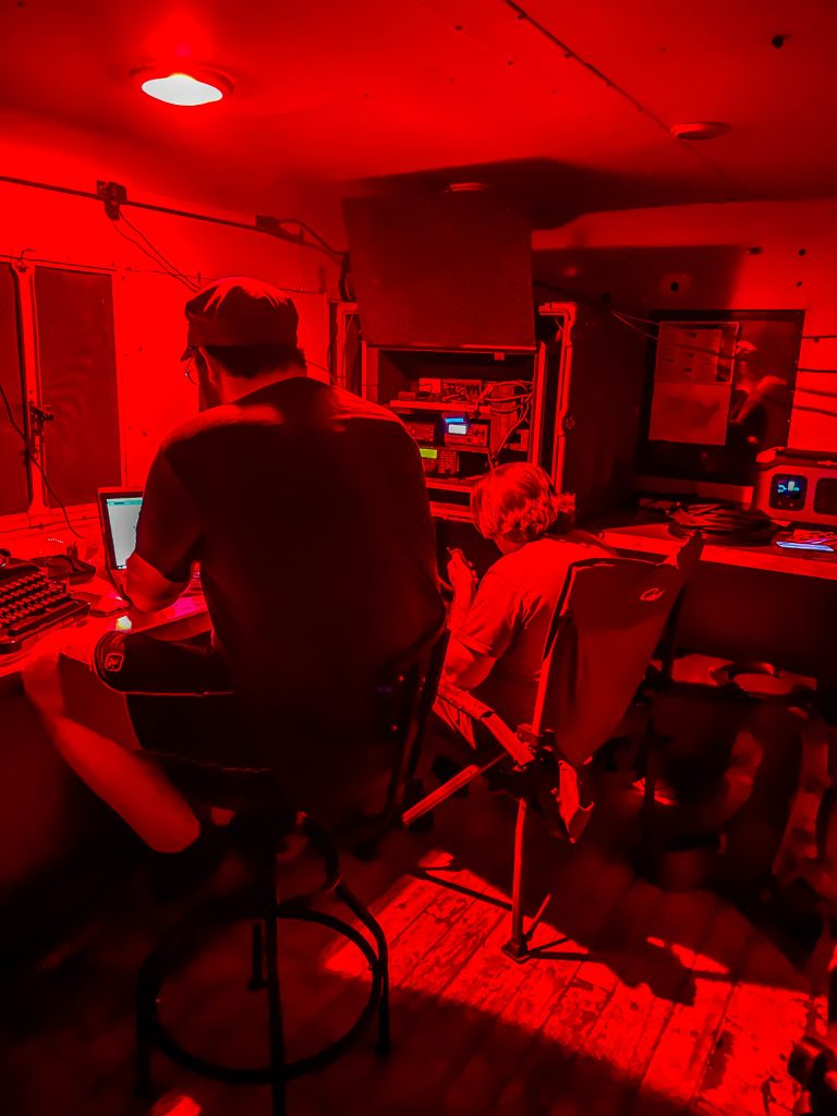
Look at your training calendar for opportunities to train the soldiers in your section primarily, and for opportunities to provide systems training to your unit in general. Your soldiers will generally enjoy unique training experiences that aren’t difficult to pull off. One example I was able to do was to send soldiers to a state park and set up an HF station so we could test some PRC-150 capabilities. This kind of thing is difficult to do ad hoc, but much easier if you get it formally scheduled. The HHB/HHC Commander is the starting point for these kinds of things, particularly if you want to involve the Battery/Company as a whole such as for training of loading radios or operator maintenance. Asking your Commo chief to make (or have made) some realistic class outlines and slides for various subjects that your section can present is useful and generally welcome for inclusion on the units training calendar.
Planning 12-24 months out gives you ample time to gather needed items for training events. Executing a good communications plan really takes some extensive groundwork to make work, you have to consider the large number of items from the antenna to the handmike. Comsec, batteries, cables, accessories, Annex H to the OPORD (and all of it’s contents), spares, and much more all have to be considered before an operation. Generally, during an operation is too late to get something, particularly if you go to a distant training area and going to home station is not feasible. I made a checklist for myself and insisted that my Commo chief had one as well of all the tasks and items we needed for an operation. If we found something missing, we added it to our checklists. Knowing what you will be expected to do well in advance gives sufficient time to order shortages, do maintenance on the critical items, and think through your plans in detail.
Knowing what equipment you have, what it can do, what its status is, and having a well thought out plan of how to use it will answer nearly all questions your Commander may have for you. Most non-signal people like straightforward, non technical, answers to questions so anticipate questions that you may be asked and how to answer these questions without diving into deep technical explanations. Having answers to the above items will increase your confidence and increase the confidence your Commander and staff will have in you.
Over the last 20 years the US Army has been fighting a counterinsurgency. Communications requirements for this is quite different than what the US Army may be facing in the future. Having been around since the 80s (Cold War era), I remember communications that favored mobility and rather complex communications security (eg SOIs with changing identifiers, frequently changing frequencies, etc). IT systems are most definitely not mobile, and while you will have to maintain and train with these items, do advocate for training with mobile systems like FM and HF from time to time. Try to anticipate how a unit might fight in a future conflict, and how you can adapt what you have to these environments. Anticipate what your potential enemies might do to disrupt your communications and what you could do in response.
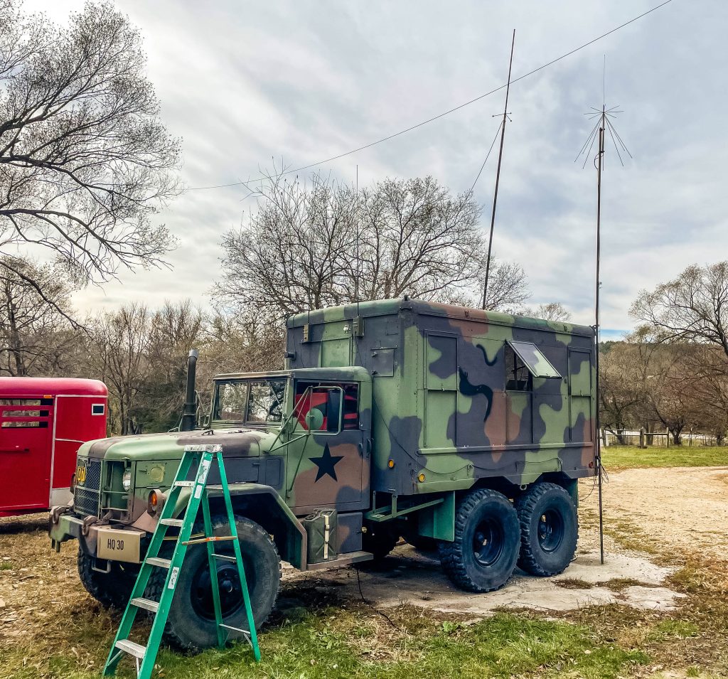
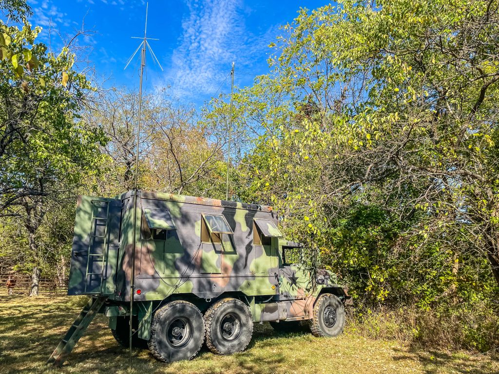
The M37 Truck came with a radio antenna, and I thought it would be nice to be able to use that. My overall goal was to make use of the equipment that came with the truck (antenna mount and LS-166 speaker), have a useable method of communication while in the truck, and have the radio appear to be ‘period correct’ (meaning the equipment would look like it would be in use in the 1950’s era). I didn’t want to ruin restorable equipment while doing this.
The actual antenna mount is an AB-15 base on AB-243 mount with antenna elements, but these are tuned for 30-90MHz, not 144-148MHz used by the 2m amateur radio I prefer to use. It is possible to use a working AN/PRC-8/9/10 on amateur radio (on 6m) but there isn’t a lot of activity there that I have found, although solar activity dictates this in cycles of which we are in a bad period. I also could have used CB but having monitored that over the last couple years in my area, I have not found anything interesting on it. That leaves 2m, which in my area is active and interesting to use. I also had an Icom 880H radio that hasn’t seen much use since I sold the car that it was in previously. Having the 880H as the working radio, I just needed the shell, and the AN/PRC-8/9/10 series of radios had it all – it looks great, is of the correct time period, and is large enough to contain the 880H.
Painting may not be needed depending on the condition of the set, but the example I had needed it. The paint must be thin to look correct. Painting of the raised letters worked with a stiff rubber applicator while painting upside down to discourage paint wicking. Paint that flows outside of where it is supposed to go can be gently removed with magnifier, an exacto, and patience after it dries. I used POR-15 as primer since I had some for another project, but it appears to adhere quite tenaciously and should be a good choice, as long as it is applied thinly.
For the electronics, I couldn’t escape using the Icom HM-133 hand mike circuit board since it uses bitstreams to code PTT on and off. The PTT trigger is very sensitive and would key up when connecting any kind of mechanical switch which is why I used a photo isolating switch for it. The HM-133 required de soldering of the PTT switch and the microphone element. I soldered wire leads from those holes to their destinations and there is little room to work with, but it worked. The HM-133 is in a block of foam cut to keep it in place with a plastic cover on it to prevent shorting. Schematics in the previous post.
I was able to preserve the function of the original on/off rotary switch as an on/off switch for the PTT and display LEDs, but the Icom 880H control head still powers the 880H on/off. The volume and squelch of the original I could not find a straightforward method of adapting these, but it might be possible later. The tuning knob and display of the original still works visually but had no effect on the radio operation. It does look nice cleaned up and illuminated, however.
Internal wiring is a balancing act of having enough to disassemble, but not so much as to no longer fit. I oriented it with the 880H fan facing the rear so hot air could leave via a vent hole I cut in the PRC-9 battery box. It would have been more convenient for wiring if it was the other way, but it would have no place to vent. This vent and the hole for external speaker, power, and 880H control head line is concealed by the (very handy) swing out feet on the battery box.
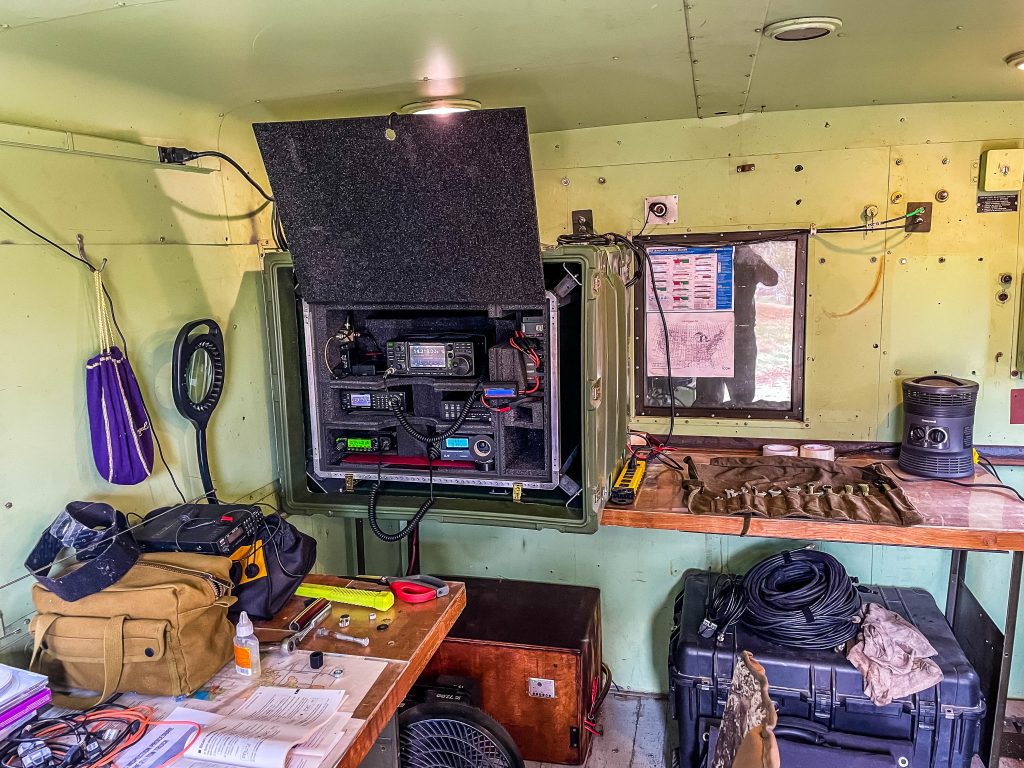
When I get the truck back ill find a way to mount it in there but finding references on installing radios in the M37 are scarce. I find some reference to mounting in the truck bed, but I’ll try to adapt something to the cab.
I was looking for an old, unrepairable radio to hide an Icom 880H Amateur radio in and found a perfect example. This radio would be period appropriate, being produced in the 50s and its even the Artillery type, good match for my 2-130th Field Artillery marked truck. I wanted unrepairable since I didn’t want to mess up a potentially good radio and ruin some history. I got this from http://fairradio.com/ Fair Radio Sales who took the time to dig up a salvage radio for me. I hope to get one of their repairable AN/PRC-9 radios soon as well, maybe an AN/GRR-5 too.
The M37 truck has an antenna, antenna mount, and working speaker on it, but no radio base, so I’ll have to come up with a way to mount the radio, but it will be neat to have a working radio as I am driving the truck.
The AN/PRC-8, 9, and 10 series of radios came in versions for Armor (AN/PRC-8), Artillery (AN/PRC-9), and Infantry (AN/PRC-10). AN/PRC stands for Army/Navy Portable Radio Communications. A good article describing the series can be found at http://www.n6cc.com/prc-10-infantry-radio/. As a signal officer, I am glad they abandoned the Armor/Artillery/Infantry versions, but it likely was a good way to make this set (more) portable given the technology of the time. It is quite a compact radio, surprisingly, the Icom 880H just fits in the battery case.
I asked for a salvage radio, and this example was quite corroded inside, thus not really salvageable; but this is what I wanted as it will just be a place to hide the Icom 880H. I will preserve the tune dial gearing which is still running smoothly, rewire the handmike to work with the Icom, and maybe try to repurpose the dials to change channels or volume control. The Icom 880H has a remote control head which can mount in the glovebox to be handy, but not visible.
I have heard good things about POR-15 and I’ll try it on this radio. Topcoat will be OD Green. As I get the wiring and mounting worked out, I will post these details.
Restoration and Adaptation of AN/PRC-9 (August 2022)
POR-15 will be great, it is tough stuff, but I put it on too thick. One thin layer of it then OD green would have been sufficient. I did two, I’ll strip it and start over. The paint pen also isn’t going to work, partially because it flows to fast and is not crisp, but the thick layer of paint isn’t helping either. I am not sure how I will tackle the fine, crisp lines needed for the raised metal. Stencils for the original markings should be doable (ORG, CH, POINTER ADJUST labels), but the raised metal is going to be a challenge.
The battery box will work great for the ID-880H, but sadly I’ll have to cut a hole somewhere for power, I/O, and ventilation. There is a handy stand built right into the battery box, two legs that swing out, that could be a good candidate for hiding a hole underneath. The battery box was beat up, but I was able to (slowly) coax it back into shape with a softwood lever.
Painting, take two
POR-15 is difficult to strip, which means it’s tough and durable so that is ultimately good news. Modern stripper won’t remove it, but it does soften it enough to gently pick it off with and Exacto knife. Tedious be effective, just be cautious about gouging the surface of the metal.
The local hobby store in Topeka (Dee and Me Hobbies) suggested paint on a piece of glass or something and press the paint on. It seems to work well, but glass seems too stiff causing paint not to apply, and standard rubber is too soft which causes paint to flow past the letter faces. I found a drill bit holder that looks to have promise, made of stiff rubber. I’m applying an even, thin coat of paint then pressing it on the letter faces. I’ll get some practice then try again.
Second Coat of Paint and Padding for 880H (September 2022)
Turned out much better with a very thin coat of paint. The letters are crisp and should be easier to paint. I cut an 1 1/2 in hole in the battery box where the 880H vent is to get warm air out of the setup. I used a Dremel to make the rough cut and a round file to finish. I’ll get a rubber gromet for the vent and the power connection. The foam is some stuff I had lying around, and it will work great. Not too hard to cut and will cushion the radio while getting bumped around as I am driving.
I found a very helpful person that has Icom microphone elements, which I will use rather than adapting the old carbon mic in the H-33 military mic. It should be straightforward to hook up since it will be an Icom element.
I hooked up the radio in the battery box and listened to the local NOAA weather station, it was slightly muffled, but not as bad as I thought. The truck has military speaker as well that I will hook this radio too, I should be able to hear even while driving with little issue.
Adapting Icom HM-133 handmike to H-33
I didn’t really think about it when I first thought this up but wiring this won’t be as simple as reconnecting wires around. The microphone and handset speaker isn’t the same between the HM-133 (Icom) and H-33 (mil). The circuitboard in the HM-133 provides some supporting electronics along with some voltage. The actual (tiny) microphone in the HM-133 isn’t labeled either, it surprised me to find how miniature the mic is compared with the H-33 carbon mic.
I have some choices to make in wiring this. I can convert the audio from the mic/handset speaker/radio to the original elements in the H-33 somehow, use modern mic/speakers in the H-33 and assemble an approximation of the supporting electronics, or just take the circuit board from the HM-133 and put that whole thing in the radio and feed the (modern) mic element from it. Finding information on the components is difficult, but I finally found a resource I can use to understand more clearly what I am doing. https://www.tinymicros.com/wiki/Icom_HM-133 has extensive notes and links to datasheets on the components, including the specific mic, a Hosiden KUB2823 Microphone, at least that looks correct. Now instead of guessing what needs what if I make some supporting electronics, I can do this accurately.
I did get a collection of scrap components from https://www.7000mic.com/, which gives me some great options, but I really need to dig into the datasheets of these components, understand what they need and can do, so I am not needlessly wasting these items.
The earpiece hopefully will be straightforward, there is a speaker jack in the back of the radio I can use to feed the military loudspeaker in the truck and the earphone in the H-33, although I will have to get specific about what is being output at this jack and what the two speakers expect. Interestingly, one of modern earpiece speaker elements I have fits perfectly in the spot the old mil element did.
If I do end up just using the whole circuitboard from the HM-133, there is plenty of room in the AN/PRC-9 body to fit, since the components have been cleared out it minus the freq dial and gearing which I will preserve to keep the appearance of an AN/PRC-9.
As a Signal officer, I know electricity and radio theory basics, but I never really had to dig too far down into determining what a schematic is telling me. My enlisted days after being a 13B cannoner, in my 25 series signaller time, I did tuning of 12 series radios but that was a long time ago and I didn’t really have to interpret schematics as much as just know what to look for and what components might need replaced. I soldered and turned pots alot, but never really dug into ~why~ the circuits were as they were. Modern radios lend themselves even less to this as they generally get repaired by board replacement, which I found right before I went to OCS in my last days in the electronics shop with the SINCGARS. I really need to dig down and understand clearly what I can and should do in hooking this up to get a good result.
Once I get the right combo and get it working I will detail how I got there, the notes and links at https://www.tinymicros.com/wiki/Icom_HM-98/HM-133_Internals should get me on the right path. I have quite alot of study ahead of me, even though I wasn’t expecting it, I am happy to learn about something I have been wanting to understand for many years, electronics.
Getting Started with Connections
I found some old speakers that were trash and got the speaker cable from that. On the U77/U79 connector, pins A and B are the speaker, so I soldered those in, plugged in the cable, and got audio through. I have to test the PTT function on the radio and how to get the mic part through. PTT on this radio appears to be more than just a press switch, the HM-133 sends a bitstream to PTT then a bitstream to key off. There is a PTT on the schematic that may just be simple key on/off and I’ll have to test that, but I am not optimistic. If it does not, I’ll have to see the behavior of the HM-133 PTT and see how I can extend that.
Mapping the U77/U79 connector to the 880H RJ45 jack should be straightforward from a physical wire perspective, but what properly goes where will be another story. Up next will be testing behavior of PTT and mic to see what my options for extending those are.
H-33 Military Handmike
This mic has been confusing me for a bit, I really didn’t want to totally disassemble it, but continuity checks were not agreeing with documents I have found.
If I am to use the HM-133 circuitboard, I will need two wires for speaker, two wires for mic, and two wires for PTT. In testing the PTT from the HM-133, its a simple push switch so I can just loop in the H-33 PTT (F and H, brown and yellow), but the brown cable didn’t pass continuity. I exposed the wires on the H-33 and connected at the end of the brown on each side and found that if I flex the coiled wire, I get connection sometimes – meaning the cable itself is shot internally. Since I purchased this as a non-working display piece, this is fine/expected but I’ll have to get a replacement coiled wire or simply use another H-33. At least I got to see the U77 connector disassembled, which is surprisingly easier than I anticipated.
My current plan is to use A/B for speaker, C/D for mic, and F/H for PTT. My simple RadioShack soldering iron that I have had for decades really isn’t sufficient for this (tip to large and burned up), so I got a better Weller iron. I really wanted a Weller 1010 but went with the consumer 30w version for a third as much and it will do what I need done. I also found an assortment pack of diodes, resistors, capacitors, LEDs, and breadboard since I really need to get better with electronics. I need to be more like Sayid from Lost – he could build radios from junk like all signal officers should be able to.
October Progress
Painting the raised letters and getting an acceptable result was a challenge, but I was able to accomplish this using the stiff rubber drill bit holder (any flat piece of stiff rubber with just a little give would work) and painting this while holding it upside down. I used an Exacto to gently scrape paint the flowed/wicked despite being upside down. I would guess there is a better technique out there, but I couldn’t find it and I ended up with a decent result. The tuning knob works to move the frequency dial even if this isn’t connected to anything. Ill place an LED where the incandescent bulb was to illuminate the dial like the original.
The PTT problem was difficult to overcome, but I think I have it nailed. The U79 had oil in it to free the pins and this appeared to be just conductive enough to trigger the very sensitive HM-133 PTT circuit. Disassembly of the U79 as easier than I thought, and after cleaning it, the U79 no longer triggers the HM-133 PTT. The H-33 PTT still does trigger the HM-133, even after detailed cleaning. I was able to overcome this with a photo coupler – test rig below:
I bought an assortment of electronic components and it had a photo sensitive resistor and LEDs, so I hooked the H-33 PTT to light and LED and the HM-133 on the photo resistor. This worked reliably and I was able to make a test call on 2m using the H-33 fully set up. I will order a PC817 Optocoupler for the final assembly. With the last technical issues out of the way, I can work on final assembly and get it in service.
Finishing up
The radio is complete. The photo coupler solves the touchy HM-133 PTT problem reliably. I did put some electrical tape over the contacts in the mil H-33 PTT as it seemed to cause the LEDs to flicker sometimes without it, likely since they are slightly compressed when assembled and the connector leads are very close together. 10 Ohm resistors used to bring the buck delivered voltage down a bit from the top edge of the LED specifications. Talked to someone on 2m that stated my audio was good, so this setup seems complete electrically.
Now that it is complete, I will post the details in a separate post since this post was long and has some wrong turns in it. I also have to stencil on the ORG/CH table that was on the original to be completely done, but this will go nicely with the M37 when it is finished. Most photos of the M37 with a radio shows it mounted in the bed area, but I would like this radio in the cab. Hopefully I can find a photo of such a setup.
My engine suffered a broken crankshaft and broken piston. Not bad after nearly 70 years. I knew that a rebuild would be needed at some point and wondered how much this would cost. Now that I am doing an engine/transmission rebuild, I (will) have the answer.
All parts came from the very helpful staff at http://www.vintagepowerwagons.com/ who have been willing to take some time to guide me with parts choices based on their experience. Information like what things wear and should be periodically replaced was very helpful.
Parts breakdown (prices are rounded, some minor items omitted, ask VPW for recommendations):
Part
Notes
Cost
Crankshaft
Only required if broken or out of spec, difficult to get, shipping very expensive
Original ball joint was worn, you can’t replace the ball on the original, VPW had a rebuilt original for a good price. I had an idler arm that came with the truck
$50
Brake Line Set (steel w spring protector)
Vintage Power Wagons sells a complete set of brake lines. Getting under the vehicle showed some corrosion on the lines and the brake light switch section was falling apart so decided to just replace everything
$250
Brake light switch set (Packard)
Packard connectors seem to be more stable than the original shell types
$50
Radiator Recore
Done at B & D Radiator Shop in McLouth KS. Last army depot went bananas with solder so B&D cleaned that up and recored it since this old radiator was devolving pinholes.
$700
Transmission rebuild
Done at Smith Brothers, Topeka http://www.smithbrotherstransmission.com/ – Took a bit to find a shop interested in this transmission, was happy to find a shop that seemed genuinely interested in getting this old truck back in motion
Retired mechanic with good reputation and familiarity with Dodge Power Wagons
Pending, estimate 3-4k
Total
Pending, $12-16k?
Parts are still available but getting difficult to find. None of this has been fast, or cheap. I was able to save money on shipping by picking up the parts, Vintage Power Wagons is only about 4 hours away. My initial guess as to what this might cost was very wrong, it is about double triple what I thought it might be. Once I have final numbers, I’ll provide rounded figures in case someone has the same question I had about scale of pricing for a Dodge M37 engine/transmission rebuild.
Finding parts for early versions of equipment has been a challenge. Improvements to equipment results in the old part being removed from inventory and the new parts being stocked. For my M101 made in 1953 (coincidentally the same year as the truck) it did not come with service brake levers, and it appears they were removed quite a long time ago. The previous owner had purchased M101 levers, but they are the newer improved type, and the bracket did not fit, and even if it did would not engage the brake cable correctly.
After some extensive research I found the brake lever type and a source for the handles, but not the brackets they mount to. I got the handles from http://powderriverordnance.com – who has an interesting selection of parts and manuals. The brackets simply couldn’t be found, but I asked a local machine shop if they could make one from photos and the trailer and they stated they could. The staff at http://meridenmachineshop.com / http://www.randsmaintenance.com were very helpful and did a very high quality job making and fitting the parts.
I’ll have to adjust the brakes now, since the cables aren’t set, and then test it, but I know the levers on the drums work from when I serviced the wheel hubs and the levers/cables work so I just have to tension them appropriately now. Once that it done, I can park and disconnect this trailer safely without fear of it rolling away. I have read that these levers tend to pinch your hand, which may be why they were replaced, so I’ll have to wear gloves when operating them which isn’t really a bad idea in any case when disconnecting the trailer.
I have the later style M101 brake levers if someone needs that type, I cannot use them with my setup.
is to blow the engine. After nearly 70 years, the engine finally gave up, breaking the crankshaft and breaking a piston. Fortunately, the block appears to be ok.
Since this is a major repair, I am going to take this opportunity to replace all worn parts in the engine and transmission, hopefully getting another 70 years out of it. Ill detail the costs and parts list associated with this in case anyone is considering a major overhaul for their M37.
This engine lacked power but started and ran well for about 750 miles that I drove it. It suddenly started making a loud clunking sound on a trip which caused me to shut it off and start looking for a way to get it repaired.
At least when it’s done I should resolve that rear main oil leak that has been bugging me.
After completing this project my truck went from having a variable, but not overheated temp, to stable. The heater works too, just in time for summer. I don’t think I will use acid routinely, but it seemed very effective for use every few years. The procedure I used is below.
TM 9-2320-212-20
9/16 in wrench(s)
1/2 in wrench(s)
Screwdrivers
Water distribution tube
Thermostat gasket (there are two, the housing base gasket, and the top of the thermostat has one inside the thermostat housing)
Bypass elbow gasket
Water pump gasket
Hoses/Belt if you need to replace those, I did in this project
2 ½ -5 lb Oxalic acid (2 ½ lb per flush)
2 ½ lb Washing soda (sodium carbonate)
2 ½ lb Borax
1. Drain the coolant using the drain cocks – Open the one on the front of the radiator first, to capture as much coolant as possible to reuse or dispose of properly. After its clear, open the drain on the engine block (near the oil filler tube) to finish. The drain cock on the engine block was jammed up with gunk on my vehicle, I had to lance it (gently) a few times with stiff wire to get it to drain. You can remove the whole drain cock with a 9/16 wrench to increase flow or clear obstructions.
I recovered the coolant, filtering it through a colander/tee shirt since it is less than a year old. Letting it sit a few hours/overnight lets anything not coolant settle to the bottom to be discarded.
2. Remove the thermostat – This will ensure that any flush cycles through the system without obstruction and is straightforward to do, 2 9/16ths bolts are what holds it on. It takes some maneuvering to remove without gouging the thermostat, TM -20 page 2-118 illustrates this well, removing the bypass elbow simultaneously makes this easier if you have the gasket. For the flush cycles, I reused the old gaskets since minor leaks wont matter at this point.
3. Water Flush – I used a garden hose and set the flow to match the drain rate with the drain cock on the radiator removed, then ran the engine while closely monitoring to ensure the water level stayed full. This forces water to move through the system and exit the bottom of the radiator. I also alternated between radiator drain cock and block drain cock, but did not have the engine running while the block drain cock was open. I did this for about 10 minutes.
4. Acid Flush – I mixed 1 cup (about 8oz) of oxalic acid per gallon, and the cooling system capacity is 4.25 gallon – I mixed 4 gallons of this solution. The TM -20 page 2-116 mentions both aluminum chloride and oxalic acid, I could not find a source of aluminum chloride, nor a reference for its use in corrosion removal. I did find several references to oxalic acid in cooling system maintenance, so I used it by itself. I did 2 cycles of acid flush, driving the vehicle both times to bring up to running temp. Both cycles came out florescent green (much like antifreeze) which appears to be the color of rust dissolved in oxalic acid (ferric oxalate) – Cleaning with Oxalic Acid? Here’s What You Need to Know. – CORECHEM Inc. – All About Ferric Oxalate (bostick-sullivan.com)
5. Water flush – same as 3
6. Soap flush – same as 3 but with detergent (laundry or dishwasher to reduce suds). Not mentioned in the TM, but I have read several internet references on this and I imagine it would be beneficial to remove any oils that somehow remained after the above.
7. Neutralize – Washing soda (sodium carbonate), 8oz per gallon, running to circulate. The TM mentions Borax as an ‘inhibitor’, which I will use second to last flush before adding coolant when finished. Borax isn’t particularly PH basic (PH 9), and am not sure why the TM states to use it, but its cheap and more flushing can’t hurt.
8. Water flush – same as 3
9. Disassemble the cooling system – These steps are to get to the coolant distribution tube, which is apparently liable to get clogged and if it does cools unevenly. Uneven cooling would result in the front cylinder getting adequate cooling and the rear getting less as the water travels down the tube from front to back.
10. Remove tension from the belt – My truck gets belt tension from the alternator, loosening the tension bolt permits the belt to slip of the alternator. Evaluate the belt for replacement, I will replace mine.
11. Remove the fan – its straightforward, using 4 1/2in bolts, this is illustrated on page 2-121. The spacer part will fall out as it isn’t attached to the fan or water pump. Be careful not to gouge the radiator when removing this.
12. Remove the 6 radiator and fan shroud bolts – The bolts on my truck appear to have wire holes to prevent them from turning when installed, but no wire was installed. I used thin boards to support and cushion the radiator when it came loose as the last bolts were removed.
13. Remove the radiator hoses – Page 2-115 illustrates this well, there is the inlet and outlet hose/tubes. Evaluate them for replacement, I will replace mine.
14. Remove the shroud and radiator – Remove the fan shroud being carful not to gouge the radiator, then remove the radiator. It is possible to do this solo, but easier to do with two people.
15. Remove the water pump – there are three 9/16 bolts holding the water pump on, remove these and take off the water pump.
16. Remove/replace the water distribution tube – behind the water pump is the water distribution tube, remove with a tool from Vintage Power Wagons http://www.vintagepowerwagons.com/ (Part #NTP211), I replaced with the Vintage Power Wagon stainless steel tube Part #CC637432. I flushed out the empty water distro tube channel using a hose attachment/wand that got me to the rear of the block to flush things out instead of spraying debris further in.
17. Clean the system surfaces – gasket interfaces, hose connections, and other parts all were thoroughly cleaned (washed and wire wheeled where needed). I spray painted the fan shroud and tubes with black engine paint, and the radiator body (not cooling tubes) with green paint from Army Jeep Parts – Gillespie Coatings Paint | Military Paint | Army Jeep Parts
18. Flush the radiator – My radiator overflow pipe (the small tube from filler neck to the bottom of the radiator for overflow fluids to exit) had been clogged, causing coolant to spray all over the engine from time to time. Solving this issue was fairly easy, I used electric fence wire to lance the tube, clear the blockage, then flush it out. The radiator itself benefited from being able to tilt from side to side, dislodging more debris in the bottom and flushing it out with a hose. Use caution and don’t batter the radiator while doing this.
19. Install the radiator and fan shroud – Use thin boards to cushion the radiator as it is placed. I wired my radiator bolts so they wouldn’t loosen, but it seemed fine without it. The bolts are drilled for wire, so it seemed like it should be done. I used electric fence wire, which should be durable and not prone to corrosion as it is made to be in the weather. I have no idea if this tie is correct, but I assume it will prevent the bolt from turning.
20. Install water pump – using a thin coat of sealant on both sides of the gasket, replace the water pump and gasket
21. Put the belt in place
22. Install the fan and fan drive pulley, orchestrating all this is tricky with the space available, but possible with patience.
24. Install the thermostat, inlet/outlet hoses, and heater hoses if you have those. The bypass elbow and thermostat housing have to be installed together, there isn’t enough hose between them to maneuver the thermostat in place otherwise.
25. More flush cycles, Borax then water. Check for leaks and test drive.
26. Fill with distilled water and antifreeze and bring to temp to ensure its mixed well